How to Use Pololu 5V, 2.5A Step-Down Voltage Regulator D24V22F5: Examples, Pinouts, and Specs
Introduction
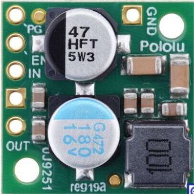
The Pololu 5V, 2.5A Step-Down Voltage Regulator D24V22F5 is a compact and efficient DC-DC buck converter designed to step down a higher input voltage to a stable 5V output. With a maximum output current of 2.5A, this regulator is ideal for powering microcontrollers, sensors, and other low-voltage devices in a variety of applications. Its small size and high efficiency make it suitable for portable electronics, robotics, and embedded systems.
Explore Projects Built with Pololu 5V, 2.5A Step-Down Voltage Regulator D24V22F5


Explore Projects Built with Pololu 5V, 2.5A Step-Down Voltage Regulator D24V22F5
Common Applications
- Powering microcontrollers such as Arduino, Raspberry Pi, and ESP32.
- Supplying 5V to sensors, servos, and other peripherals in robotics.
- Voltage regulation in battery-powered devices.
- General-purpose 5V power supply for embedded systems.
Technical Specifications
Key Specifications
| Parameter | Value |
|---|---|
| Input Voltage Range | 6V to 38V |
| Output Voltage | 5V (fixed) |
| Maximum Output Current | 2.5A |
| Efficiency | Up to 95% |
| Quiescent Current | ~1 mA |
| Switching Frequency | ~470 kHz |
| Operating Temperature | -40°C to +85°C |
| Dimensions | 0.7" × 0.8" × 0.15" (18 × 20 × 4 mm) |
| Weight | 1.2 g |
Pin Configuration
The Pololu D24V22F5 regulator has six pins. The table below describes each pin:
| Pin Name | Description |
|---|---|
| VIN | Input voltage pin. Connect to the higher voltage source (6V to 38V). |
| GND | Ground pin. Connect to the ground of the circuit. |
| VOUT | Regulated 5V output pin. Connect to the load requiring 5V. |
| ENABLE | Enable pin. Drive high (or leave unconnected) to enable the regulator. |
| PG (Power Good) | Open-drain output that indicates if the output voltage is in range. |
| FB (Feedback) | Feedback pin for advanced users (not typically used in standard setups). |
Usage Instructions
How to Use the Component in a Circuit
Connect the Input Voltage (VIN):
- Attach the VIN pin to a DC voltage source within the range of 6V to 38V.
- Ensure the input voltage is stable and does not exceed the maximum rating.
Connect the Ground (GND):
- Connect the GND pin to the ground of your circuit.
Connect the Output Voltage (VOUT):
- Attach the VOUT pin to the device or circuit requiring a 5V power supply.
- Ensure the connected load does not exceed the maximum output current of 2.5A.
Enable the Regulator:
- The ENABLE pin can be left unconnected or driven high (logic level) to enable the regulator.
- To disable the regulator, pull the ENABLE pin low.
Optional Connections:
- Use the PG pin to monitor the output voltage status. This pin will be low if the output voltage is out of range.
- The FB pin is for advanced configurations and is not required for standard use.
Important Considerations and Best Practices
- Heat Dissipation: Although the regulator is highly efficient, it may generate heat under high loads. Ensure adequate ventilation or heat sinking if operating near the maximum current.
- Input Voltage Range: Always ensure the input voltage stays within the specified range (6V to 38V) to avoid damaging the regulator.
- Capacitors: For optimal performance, use appropriate input and output capacitors as recommended in the Pololu datasheet.
- Polarity Protection: Double-check the polarity of the input voltage to prevent damage to the regulator.
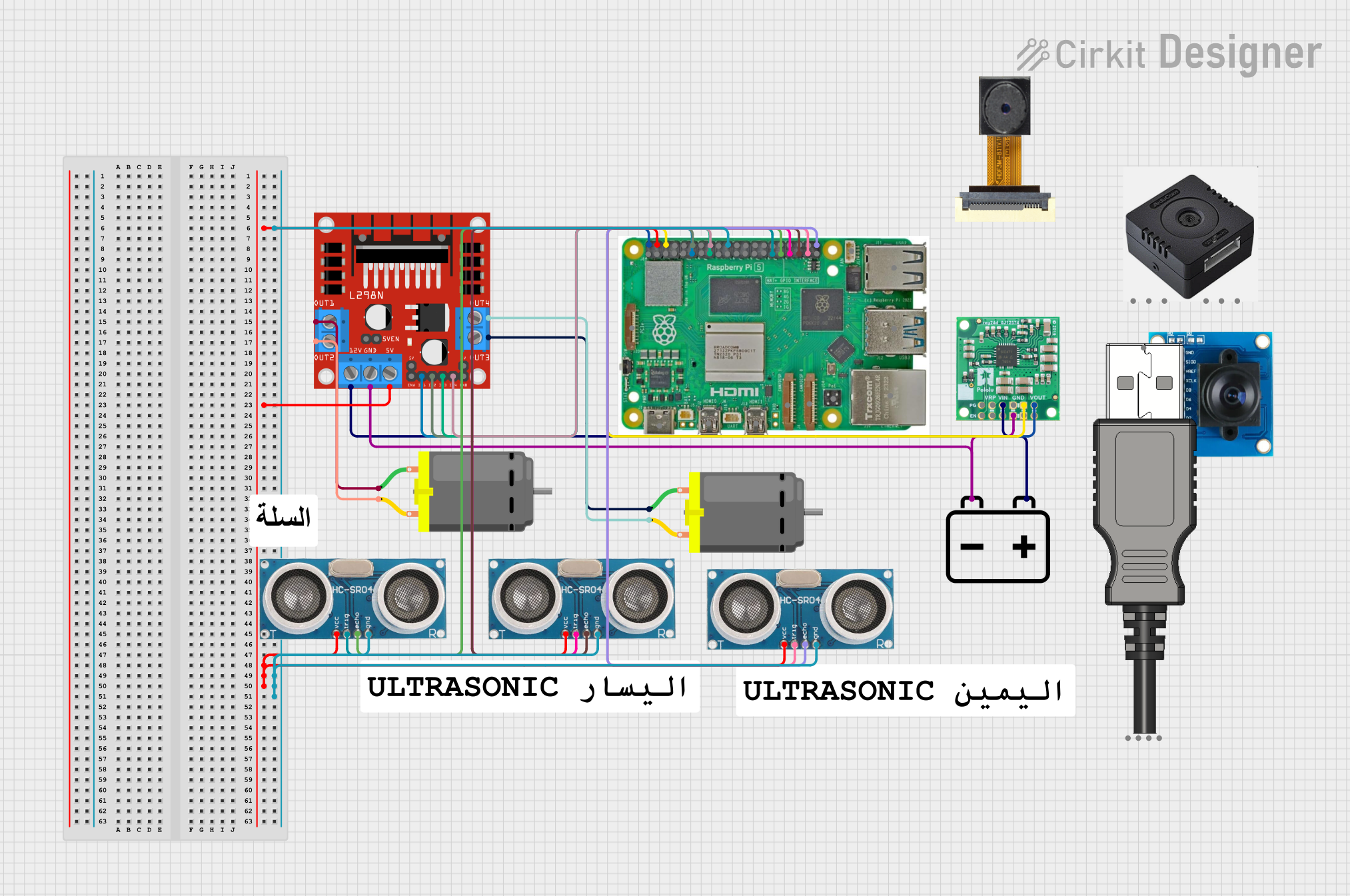
Example: Using with Arduino UNO
The Pololu D24V22F5 can be used to power an Arduino UNO by stepping down a higher voltage (e.g., 12V) to 5V. Below is an example wiring diagram and Arduino code:
Wiring Diagram
- Connect the VIN pin of the regulator to a 12V DC power source.
- Connect the GND pin of the regulator to the ground of the power source and Arduino.
- Connect the VOUT pin of the regulator to the 5V pin of the Arduino UNO.
Arduino Code Example
// Example code to blink an LED connected to pin 13 of Arduino UNO
// Ensure the Arduino is powered via the Pololu regulator's 5V output.

void setup() {
  pinMode(13, OUTPUT); // Set pin 13 as an output
}

void loop() {
  digitalWrite(13, HIGH); // Turn the LED on
  delay(1000);            // Wait for 1 second
  digitalWrite(13, LOW);  // Turn the LED off
  delay(1000);            // Wait for 1 second
}
Troubleshooting and FAQs
Common Issues and Solutions
No Output Voltage:
- Verify that the input voltage is within the specified range (6V to 38V).
- Check the ENABLE pin. Ensure it is left unconnected or driven high.
- Inspect all connections for loose wires or incorrect polarity.
Overheating:
- Ensure the load does not exceed 2.5A.
- Improve ventilation or add a heat sink if the regulator is operating near its maximum current.
Output Voltage Fluctuations:
- Add appropriate input and output capacitors as recommended in the datasheet.
- Ensure the input voltage is stable and free from significant noise.
PG Pin Always Low:
- Check if the output voltage is within the expected range.
- Verify the load is not drawing excessive current.
FAQs
Q: Can I use this regulator with a 24V battery?
A: Yes, the regulator supports input voltages up to 38V, so a 24V battery is within the acceptable range.
Q: What happens if I connect a load that requires more than 2.5A?
A: The regulator may enter thermal shutdown or current limiting to protect itself. Ensure the load does not exceed 2.5A.
Q: Is the regulator protected against reverse polarity?
A: No, the regulator does not have built-in reverse polarity protection. Always double-check your connections.
Q: Can I adjust the output voltage?
A: No, this regulator provides a fixed 5V output. For adjustable output, consider other Pololu regulators.
This concludes the documentation for the Pololu 5V, 2.5A Step-Down Voltage Regulator D24V22F5. For further details, refer to the official Pololu datasheet.