
How to Use V_REG MIC5219: Examples, Pinouts, and Specs
 Design with V_REG MIC5219 in Cirkit Designer
Introduction
The MIC5219 is a high-performance, low-dropout voltage regulator designed to provide a stable and precise output voltage. It features low noise, high power supply rejection, and low quiescent current, making it ideal for battery-powered devices. The MIC5219 is equipped with advanced features such as thermal shutdown and current limiting to ensure safe and reliable operation.
Explore Projects Built with V_REG MIC5219
 Open Project in Cirkit Designer
 Open Project in Cirkit Designer
 Open Project in Cirkit Designer
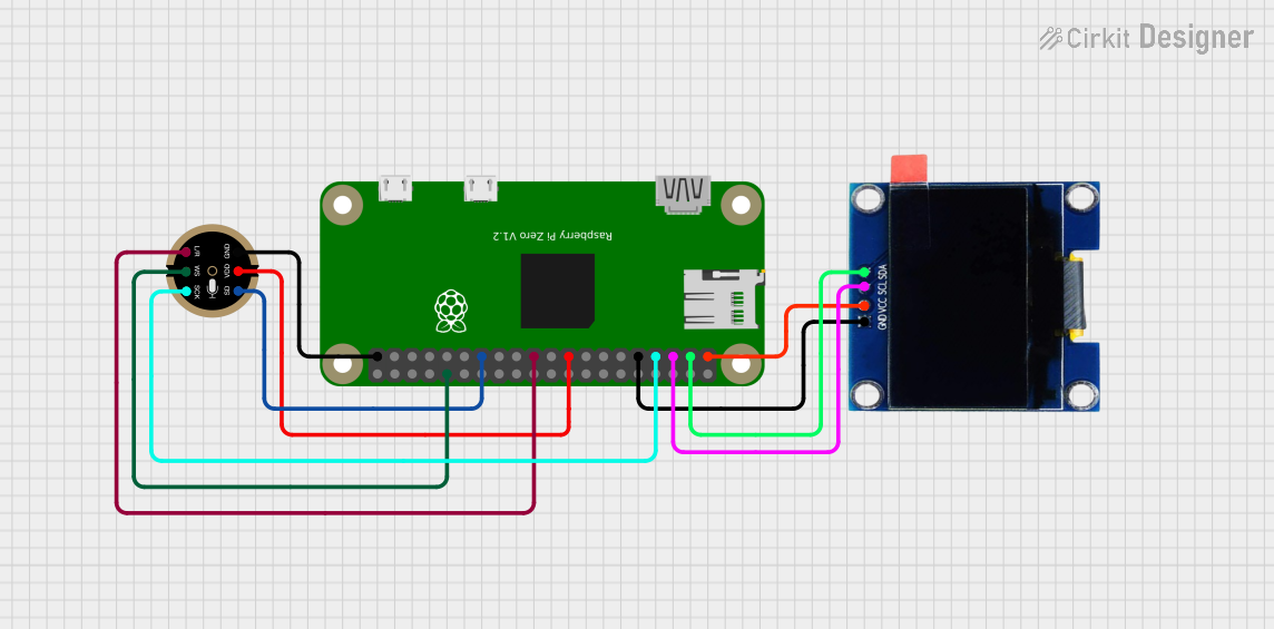 Open Project in Cirkit Designer
Explore Projects Built with V_REG MIC5219
Open Project in Cirkit DesignerOpen Project in Cirkit DesignerOpen Project in Cirkit DesignerOpen Project in Cirkit DesignerCommon Applications
- Portable and battery-powered devices
- Noise-sensitive applications such as RF systems and audio circuits
- Microcontroller and digital logic power supplies
- Low-noise instrumentation and sensor systems
Technical Specifications
Key Specifications
| Parameter | Value |
|---|---|
| Input Voltage Range | 2.5V to 12V |
| Output Voltage Range | 1.25V to 5.5V (fixed or adjustable) |
| Output Current | Up to 500mA |
| Dropout Voltage | 165mV at 150mA, 300mV at 500mA |
| Quiescent Current | 90µA (typical) |
| Output Noise | 30µVrms (10Hz to 100kHz) |
| Power Supply Rejection | 75dB at 1kHz |
| Operating Temperature Range | -40°C to +125°C |
Pin Configuration and Descriptions
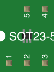
The MIC5219 is available in several package types, such as SOT-23-5 and SOT-223. Below is the pin configuration for the SOT-23-5 package:
| Pin Number | Pin Name | Description |
|---|---|---|
| 1 | VIN | Input voltage supply |
| 2 | GND | Ground connection |
| 3 | EN | Enable pin (active high) |
| 4 | ADJ/FB | Adjustable feedback pin (for adjustable versions) |
| 5 | VOUT | Regulated output voltage |
Usage Instructions
Using the MIC5219 in a Circuit
Input and Output Capacitors:
- Connect a low-ESR ceramic capacitor (typically 1µF or greater) to the input (VIN) for stability and noise filtering.
- Similarly, connect a low-ESR ceramic capacitor (1µF or greater) to the output (VOUT) to ensure stable operation.
Enable Pin (EN):
- The EN pin must be pulled high (above 2V) to enable the regulator.
- If unused, connect the EN pin to VIN to keep the regulator always enabled.
Adjustable Output Voltage:
- For adjustable versions, use a resistor divider network connected to the ADJ/FB pin to set the desired output voltage.
- The output voltage is determined by the formula:
[ V_{OUT} = V_{REF} \times \left(1 + \frac{R_1}{R_2}\right) ]
where ( V_{REF} ) is typically 1.235V.
Thermal Considerations:
- Ensure adequate heat dissipation by using proper PCB layout techniques, such as thermal vias and copper planes, especially for high-current applications.
Example: Connecting MIC5219 to an Arduino UNO
The MIC5219 can be used to power an Arduino UNO or other microcontroller boards. Below is an example circuit and code to enable the MIC5219 and provide a stable 3.3V output.
Circuit Connections
| MIC5219 Pin | Arduino Connection | Notes |
|---|---|---|
| VIN | 5V (Arduino) | Input voltage from Arduino's 5V pin |
| GND | GND (Arduino) | Common ground |
| EN | Digital Pin 7 | Enable pin controlled by Arduino |
| VOUT | 3.3V Output | Powers external 3.3V devices |
Arduino Code Example
// MIC5219 Enable Pin Example
// This code enables the MIC5219 regulator using Arduino digital pin 7.

#define MIC5219_EN 7  // Define the enable pin for the MIC5219

void setup() {
  pinMode(MIC5219_EN, OUTPUT);  // Set pin 7 as an output
  digitalWrite(MIC5219_EN, HIGH);  // Enable the MIC5219 regulator
}

void loop() {
  // The MIC5219 remains enabled in this example.
  // Add your application code here.
}
Best Practices
- Use low-ESR ceramic capacitors for optimal performance.
- Avoid exceeding the maximum input voltage (12V) to prevent damage.
- Ensure proper thermal management to avoid triggering thermal shutdown.
Troubleshooting and FAQs
Common Issues and Solutions
No Output Voltage:
- Ensure the EN pin is pulled high (above 2V).
- Verify that the input voltage is within the specified range (2.5V to 12V).
- Check for proper capacitor connections on VIN and VOUT.
Output Voltage Instability:
- Use low-ESR capacitors with the recommended values (1µF or greater).
- Verify the resistor divider network for adjustable versions is correctly calculated.
Thermal Shutdown:
- Check for excessive power dissipation.
- Improve heat dissipation by adding thermal vias or copper planes on the PCB.
High Output Noise:
- Ensure proper grounding and minimize noise coupling from other components.
- Use a larger output capacitor (e.g., 4.7µF) for better noise filtering.
FAQs
Q: Can the MIC5219 be used with a 9V battery?
A: Yes, the MIC5219 can operate with input voltages up to 12V, so a 9V battery is suitable. Ensure the output voltage and current requirements are within the regulator's specifications.
Q: What happens if the EN pin is left floating?
A: If the EN pin is left floating, the regulator may not operate correctly. It is recommended to connect the EN pin to VIN or a digital control signal.
Q: Can I use electrolytic capacitors instead of ceramic capacitors?
A: While electrolytic capacitors can be used, low-ESR ceramic capacitors are preferred for better stability and performance.
Q: How do I calculate the dropout voltage?
A: The dropout voltage depends on the output current. For example, at 150mA, the dropout voltage is typically 165mV. Refer to the datasheet for detailed dropout voltage vs. current curves.