
How to Use POWER SUPPLY 24V: Examples, Pinouts, and Specs
 Design with POWER SUPPLY 24V in Cirkit Designer
Introduction
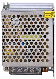
The POWER SUPPLY 24V is a device designed to convert electrical energy from an input source (such as AC mains or DC input) into a stable 24V DC output. It is widely used in powering electronic circuits, industrial equipment, automation systems, and other devices requiring a reliable 24V power source. This component ensures consistent voltage levels, protecting sensitive electronics from fluctuations and ensuring optimal performance.
Explore Projects Built with POWER SUPPLY 24V
 Open Project in Cirkit Designer
 Open Project in Cirkit Designer
 Open Project in Cirkit Designer
 Open Project in Cirkit Designer
Explore Projects Built with POWER SUPPLY 24V
Open Project in Cirkit DesignerOpen Project in Cirkit DesignerOpen Project in Cirkit DesignerOpen Project in Cirkit DesignerCommon Applications and Use Cases
- Industrial automation systems
- Robotics and motor controllers
- LED lighting systems
- Communication equipment
- Laboratory testing and prototyping
- Powering microcontrollers and sensors (via voltage regulators or converters)
Technical Specifications
Below are the key technical details of the POWER SUPPLY 24V:
| Parameter | Value |
|---|---|
| Input Voltage Range | 100-240V AC (typical) or 12-48V DC |
| Output Voltage | 24V DC |
| Output Current | 1A to 10A (varies by model) |
| Power Rating | 24W to 240W (varies by model) |
| Efficiency | Up to 90% |
| Ripple and Noise | < 100mV |
| Operating Temperature | -20°C to +70°C |
| Protection Features | Overvoltage, Overcurrent, Short Circuit, Overtemperature |
Pin Configuration and Descriptions
For a typical POWER SUPPLY 24V with screw terminal connections:
| Pin/Terminal | Label | Description |
|---|---|---|
| 1 | L | Live AC input (for AC-powered models) |
| 2 | N | Neutral AC input (for AC-powered models) |
| 3 | GND | Ground connection |
| 4 | +V | Positive 24V DC output |
| 5 | -V | Negative 24V DC output |
For DC-powered models, the input terminals are typically labeled as +VIN and -VIN.
Usage Instructions
How to Use the POWER SUPPLY 24V in a Circuit
- Verify Input Voltage: Ensure the input voltage matches the specifications of the power supply (e.g., 100-240V AC or 12-48V DC).
- Connect Input Terminals:
- For AC-powered models, connect the live (L) and neutral (N) wires to the respective terminals.
- For DC-powered models, connect the positive and negative input wires to
+VINand-VIN.
- Connect Output Terminals:
- Connect the
+Vterminal to the positive rail of your circuit. - Connect the
-Vterminal to the ground rail of your circuit.
- Connect the
- Power On: Switch on the input power source. The power supply will provide a stable 24V DC output.
- Load Connection: Ensure the connected load does not exceed the maximum current rating of the power supply.
Important Considerations and Best Practices
- Load Regulation: Avoid exceeding the rated current to prevent overheating or triggering overcurrent protection.
- Ventilation: Ensure adequate airflow around the power supply to prevent overheating, especially for high-power models.
- Grounding: Properly ground the power supply to minimize electrical noise and ensure safety.
- Polarity: Double-check the polarity of connections to avoid damaging the power supply or connected devices.
- Fuse Protection: Use an appropriate fuse on the input side to protect against surges or faults.
Example: Using POWER SUPPLY 24V with Arduino UNO
To use the POWER SUPPLY 24V with an Arduino UNO, you will need a voltage regulator (e.g., LM7805) to step down the 24V to 5V, as the Arduino operates at 5V.
Circuit Diagram
- Connect the
+Vterminal of the power supply to the input pin of the LM7805 regulator. - Connect the
-Vterminal of the power supply to the ground pin of the LM7805 and the Arduino. - Connect the output pin of the LM7805 to the 5V pin of the Arduino.
Sample Code
// Example code to blink an LED using Arduino UNO powered by a 24V power supply
// The 24V is stepped down to 5V using an LM7805 voltage regulator.

/* Connect an LED to pin 13 of the Arduino UNO with a 220-ohm resistor
   in series to limit current. */

void setup() {
  pinMode(13, OUTPUT); // Set pin 13 as an output pin
}

void loop() {
  digitalWrite(13, HIGH); // Turn the LED on
  delay(1000);            // Wait for 1 second
  digitalWrite(13, LOW);  // Turn the LED off
  delay(1000);            // Wait for 1 second
}
Troubleshooting and FAQs
Common Issues and Solutions
No Output Voltage:
- Check if the input voltage is within the specified range.
- Verify all connections, especially the input terminals.
- Ensure the power supply is switched on (if applicable).
Overheating:
- Ensure proper ventilation and avoid placing the power supply in enclosed spaces.
- Check if the connected load exceeds the rated current.
Output Voltage Fluctuations:
- Verify that the input voltage is stable.
- Check for loose connections or damaged wires.
- Ensure the load is within the power supply's rated capacity.
Short Circuit Protection Triggered:
- Disconnect the load and inspect for short circuits in the connected circuit.
- Reset the power supply (if it has a resettable protection feature).
FAQs
Q1: Can I use the POWER SUPPLY 24V to power a 12V device?
A1: No, directly powering a 12V device with a 24V power supply may damage the device. Use a step-down voltage regulator or DC-DC converter to reduce the voltage to 12V.
Q2: Is the POWER SUPPLY 24V waterproof?
A2: Most models are not waterproof. If you need to use the power supply in a wet environment, choose a model with an IP-rated enclosure.
Q3: Can I connect multiple devices to the POWER SUPPLY 24V?
A3: Yes, as long as the total current draw of all devices does not exceed the power supply's maximum current rating.
Q4: How do I know if the power supply is overloaded?
A4: Many power supplies have an LED indicator or will shut down automatically when overloaded. Check the specifications for overload protection features.