How to Use ESP32 30PIN: Examples, Pinouts, and Specs
Introduction
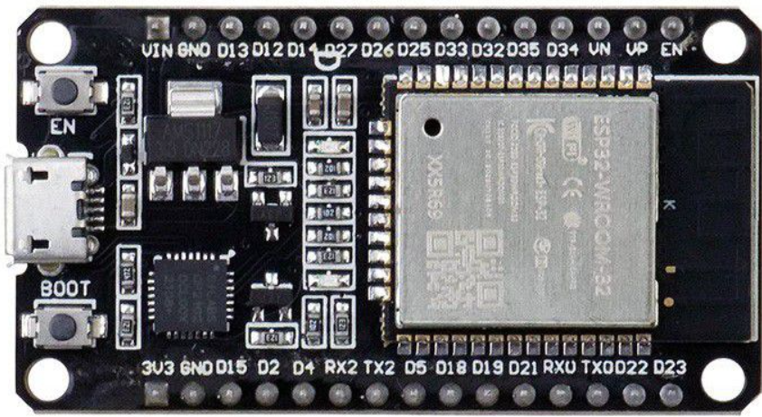
The ESP32 30PIN (Manufacturer Part ID: ESP32 DEVKIT V1 GPIO30) is a powerful and versatile microcontroller developed by ESP32. It features built-in Wi-Fi and Bluetooth capabilities, making it an excellent choice for Internet of Things (IoT) applications. With its 30 GPIO pins, the ESP32 30PIN offers extensive connectivity options for sensors, actuators, and other peripherals.
Explore Projects Built with ESP32 30PIN


Explore Projects Built with ESP32 30PIN
Common Applications and Use Cases
- IoT devices and smart home automation
- Wireless sensor networks
- Wearable technology
- Robotics and automation systems
- Data logging and remote monitoring
- Prototyping and educational projects
Technical Specifications
The ESP32 30PIN is designed to deliver high performance while maintaining low power consumption. Below are its key technical details:
| Parameter | Specification |
|---|---|
| Microcontroller | ESP32 Dual-Core Xtensa LX6 |
| Clock Speed | Up to 240 MHz |
| Flash Memory | 4 MB (varies by model) |
| SRAM | 520 KB |
| Wi-Fi | 802.11 b/g/n (2.4 GHz) |
| Bluetooth | v4.2 BR/EDR and BLE |
| Operating Voltage | 3.3V |
| Input Voltage (VIN) | 5V (via USB) |
| GPIO Pins | 30 |
| ADC Channels | 18 (12-bit resolution) |
| DAC Channels | 2 |
| PWM Channels | 16 |
| Communication Interfaces | UART, SPI, I2C, I2S, CAN, Ethernet |
| Power Consumption | Ultra-low power modes available |
| Dimensions | 51mm x 25.5mm |
Pin Configuration and Descriptions
The ESP32 30PIN has a total of 30 pins, each with specific functions. Below is the pinout description:
| Pin Number | Pin Name | Function |
|---|---|---|
| 1 | EN | Enable pin (active high) |
| 2 | IO1 | GPIO1, UART TX |
| 3 | IO3 | GPIO3, UART RX |
| 4 | IO4 | GPIO4, PWM, ADC |
| 5 | IO5 | GPIO5, PWM, ADC |
| 6 | GND | Ground |
| 7 | VIN | Input voltage (5V) |
| 8 | IO12 | GPIO12, ADC, Touch Sensor |
| 9 | IO13 | GPIO13, ADC, Touch Sensor |
| 10 | IO14 | GPIO14, PWM, ADC |
| 11 | IO15 | GPIO15, PWM, ADC |
| 12 | IO16 | GPIO16, UART RX2 |
| 13 | IO17 | GPIO17, UART TX2 |
| 14 | IO18 | GPIO18, SPI CLK |
| 15 | IO19 | GPIO19, SPI MISO |
| 16 | IO21 | GPIO21, I2C SDA |
| 17 | IO22 | GPIO22, I2C SCL |
| 18 | IO23 | GPIO23, SPI MOSI |
| 19 | IO25 | GPIO25, DAC1, ADC |
| 20 | IO26 | GPIO26, DAC2, ADC |
| 21 | IO27 | GPIO27, ADC, Touch Sensor |
| 22 | IO32 | GPIO32, ADC, Touch Sensor |
| 23 | IO33 | GPIO33, ADC, Touch Sensor |
| 24 | IO34 | GPIO34, ADC (input only) |
| 25 | IO35 | GPIO35, ADC (input only) |
| 26 | IO36 | GPIO36, ADC (input only) |
| 27 | IO39 | GPIO39, ADC (input only) |
| 28 | 3V3 | 3.3V output |
| 29 | GND | Ground |
| 30 | IO0 | GPIO0, Boot Mode Selection |
Usage Instructions
How to Use the ESP32 30PIN in a Circuit
Powering the ESP32:
- Connect the VIN pin to a 5V power source (e.g., USB or external power supply).
- Ensure the GND pin is connected to the ground of your circuit.
Programming the ESP32:
- Use a USB cable to connect the ESP32 to your computer.
- Install the necessary drivers for the ESP32 (e.g., CP210x or CH340).
- Use the Arduino IDE or ESP-IDF to write and upload code to the ESP32.
Connecting Peripherals:
- Use the GPIO pins to connect sensors, actuators, or other devices.
- Refer to the pin configuration table to select the appropriate pins for your application.
Wi-Fi and Bluetooth Setup:
- Use the built-in libraries (e.g.,
WiFi.handBluetoothSerial.hin Arduino IDE) to configure wireless communication.
- Use the built-in libraries (e.g.,
Important Considerations and Best Practices
- Voltage Levels: Ensure all connected peripherals operate at 3.3V logic levels to avoid damaging the ESP32.
- Boot Mode: GPIO0 must be pulled low during boot to enter programming mode.
- Power Supply: Use a stable power source to prevent unexpected resets or instability.
- Heat Management: The ESP32 may heat up during operation; ensure proper ventilation.
Example Code for Arduino UNO Integration
Below is an example of using the ESP32 to connect to a Wi-Fi network and send data to a server:
#include <WiFi.h> // Include the Wi-Fi library

// Replace with your network credentials
const char* ssid = "Your_SSID";
const char* password = "Your_PASSWORD";

void setup() {
  Serial.begin(115200); // Initialize serial communication
  WiFi.begin(ssid, password); // Connect to Wi-Fi

  Serial.print("Connecting to Wi-Fi");
  while (WiFi.status() != WL_CONNECTED) {
    delay(500);
    Serial.print("."); // Print dots while connecting
  }
  Serial.println("\nConnected to Wi-Fi!");
  Serial.print("IP Address: ");
  Serial.println(WiFi.localIP()); // Print the ESP32's IP address
}

void loop() {
  // Add your main code here
}
Troubleshooting and FAQs
Common Issues and Solutions
ESP32 Not Connecting to Wi-Fi:
- Double-check the SSID and password.
- Ensure the Wi-Fi network is 2.4 GHz (ESP32 does not support 5 GHz networks).
Upload Fails in Arduino IDE:
- Ensure the correct board and port are selected in the IDE.
- Press and hold the BOOT button while uploading the code.
ESP32 Keeps Resetting:
- Check the power supply for stability.
- Avoid connecting peripherals that draw excessive current.
GPIO Pins Not Working:
- Verify the pin mode is correctly set in the code (e.g.,
pinMode(pin, OUTPUT)). - Ensure the pin is not being used for another function (e.g., ADC or UART).
- Verify the pin mode is correctly set in the code (e.g.,
FAQs
Q: Can I power the ESP32 with a 3.7V LiPo battery?
A: Yes, connect the battery to the VIN pin, but ensure the battery voltage is regulated to 5V for optimal performance.
Q: How do I reset the ESP32?
A: Press the EN (Enable) button to reset the microcontroller.
Q: Can I use the ESP32 with 5V logic devices?
A: No, the ESP32 operates at 3.3V logic levels. Use a level shifter for 5V devices.
Q: Is the ESP32 compatible with Arduino libraries?
A: Yes, the ESP32 is supported by the Arduino IDE and many libraries are compatible.