
How to Use drv8313: Examples, Pinouts, and Specs
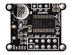
 Design with drv8313 in Cirkit Designer
Introduction
The DRV8313 is a three-phase motor driver IC designed for driving brushless DC (BLDC) motors. It integrates gate drivers, current sensing, and protection features, making it a versatile and efficient solution for motor control applications. The DRV8313 is commonly used in robotics, drones, electric vehicles, and other systems requiring precise motor control. Its compact design and robust features make it ideal for high-performance and space-constrained applications.
Explore Projects Built with drv8313
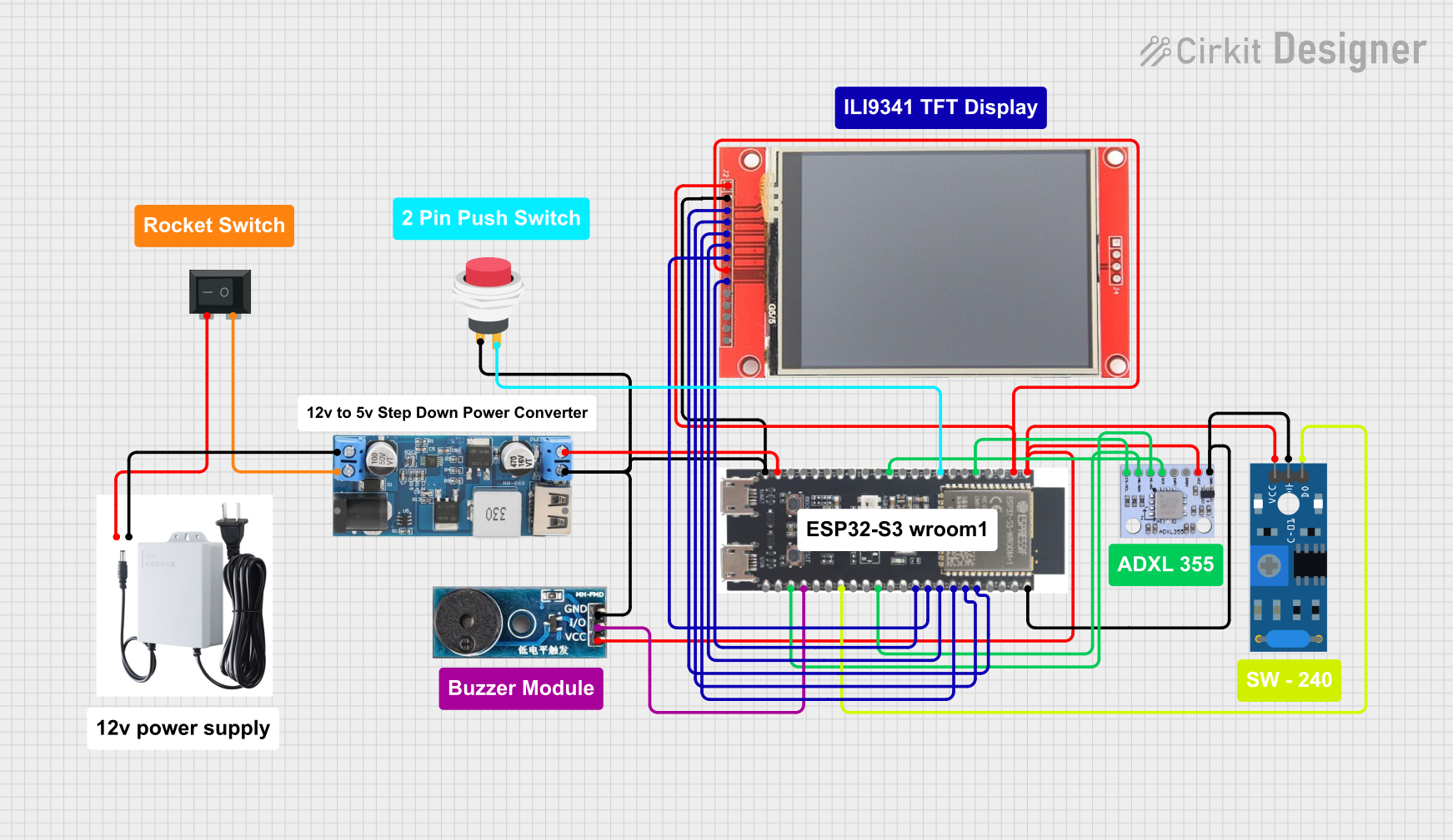 Open Project in Cirkit Designer
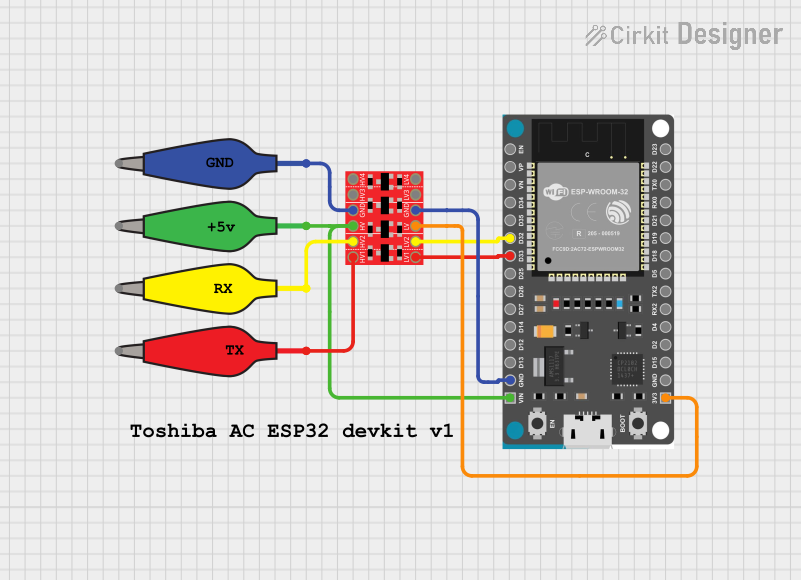 Open Project in Cirkit Designer
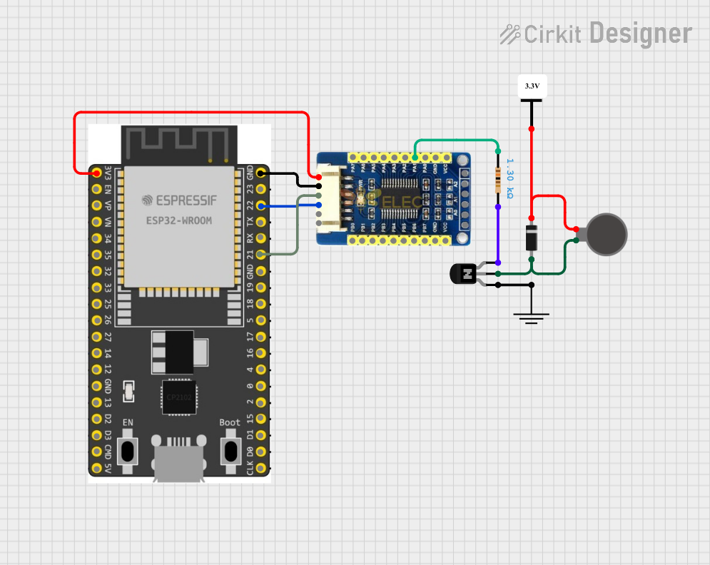 Open Project in Cirkit Designer
 Open Project in Cirkit Designer
Explore Projects Built with drv8313
Open Project in Cirkit DesignerOpen Project in Cirkit DesignerOpen Project in Cirkit DesignerOpen Project in Cirkit DesignerCommon Applications
- Robotics and automation systems
- Drones and unmanned aerial vehicles (UAVs)
- Electric vehicles and e-bikes
- Industrial machinery
- Consumer electronics with BLDC motors (e.g., fans, pumps)
Technical Specifications
Key Technical Details
| Parameter | Value |
|---|---|
| Supply Voltage (VM) | 8 V to 60 V |
| Output Current (per phase) | Up to 2.5 A (peak) |
| Control Interface | PWM (Pulse Width Modulation) |
| Operating Temperature | -40°C to 125°C |
| Protection Features | Overcurrent, overtemperature, undervoltage |
| Package Type | HTSSOP-28 |
Pin Configuration and Descriptions
| Pin Number | Pin Name | Description |
|---|---|---|
| 1 | VM | Motor power supply (8 V to 60 V) |
| 2 | GND | Ground |
| 3 | IN1 | PWM input for phase U |
| 4 | IN2 | PWM input for phase V |
| 5 | IN3 | PWM input for phase W |
| 6 | OUT1 | Output for phase U |
| 7 | OUT2 | Output for phase V |
| 8 | OUT3 | Output for phase W |
| 9 | SENSE1 | Current sense for phase U |
| 10 | SENSE2 | Current sense for phase V |
| 11 | SENSE3 | Current sense for phase W |
| 12 | ENABLE | Enable pin for the driver |
| 13 | FAULT | Fault status output |
| 14 | VREG | Internal voltage regulator output |
| 15 | NC | No connection |
Usage Instructions
How to Use the DRV8313 in a Circuit
- Power Supply: Connect the VM pin to a power supply within the range of 8 V to 60 V. Ensure the power supply can handle the current requirements of the motor.
- Motor Connections: Connect the three motor phases to the OUT1, OUT2, and OUT3 pins. Use appropriate current sense resistors on the SENSE1, SENSE2, and SENSE3 pins.
- Control Signals: Provide PWM signals to the IN1, IN2, and IN3 pins to control the motor phases. The duty cycle of the PWM signals determines the motor speed.
- Enable Pin: Pull the ENABLE pin high to activate the driver. Pull it low to disable the driver.
- Fault Monitoring: Monitor the FAULT pin for any error conditions. A low signal on this pin indicates a fault (e.g., overcurrent or overtemperature).
Important Considerations
- Use decoupling capacitors close to the VM pin to reduce noise and stabilize the power supply.
- Ensure proper heat dissipation by using a heatsink or PCB thermal vias, especially in high-current applications.
- Select appropriate current sense resistors to match the motor's current requirements.
- Avoid exceeding the maximum voltage and current ratings to prevent damage to the IC.
Example Code for Arduino UNO
Below is an example of how to control a BLDC motor using the DRV8313 and an Arduino UNO:
// Define PWM pins connected to DRV8313
const int pwmPin1 = 3; // IN1 - Phase U
const int pwmPin2 = 5; // IN2 - Phase V
const int pwmPin3 = 6; // IN3 - Phase W
const int enablePin = 7; // ENABLE pin

void setup() {
  // Set PWM and enable pins as outputs
  pinMode(pwmPin1, OUTPUT);
  pinMode(pwmPin2, OUTPUT);
  pinMode(pwmPin3, OUTPUT);
  pinMode(enablePin, OUTPUT);

  // Enable the DRV8313
  digitalWrite(enablePin, HIGH);
}

void loop() {
  // Example: Rotate motor forward
  analogWrite(pwmPin1, 128); // 50% duty cycle for phase U
  analogWrite(pwmPin2, 64);  // 25% duty cycle for phase V
  analogWrite(pwmPin3, 0);   // 0% duty cycle for phase W
  delay(2000);               // Run for 2 seconds

  // Example: Rotate motor backward
  analogWrite(pwmPin1, 0);   // 0% duty cycle for phase U
  analogWrite(pwmPin2, 128); // 50% duty cycle for phase V
  analogWrite(pwmPin3, 64);  // 25% duty cycle for phase W
  delay(2000);               // Run for 2 seconds
}
Notes:
- Adjust the
analogWritevalues to control the motor speed and direction. - Ensure the motor is compatible with the DRV8313's voltage and current ratings.
Troubleshooting and FAQs
Common Issues and Solutions
Motor Does Not Spin:
- Verify that the ENABLE pin is pulled high.
- Check the PWM signals on the IN1, IN2, and IN3 pins.
- Ensure the motor is properly connected to the OUT1, OUT2, and OUT3 pins.
Overheating:
- Ensure proper heat dissipation using a heatsink or thermal vias.
- Check for excessive current draw from the motor.
Fault Pin is Low:
- Check for overcurrent or overtemperature conditions.
- Verify the power supply voltage is within the specified range.
No Output Voltage:
- Confirm that the VM pin is receiving the correct voltage.
- Ensure the current sense resistors are properly connected.
FAQs
Q: Can the DRV8313 drive a brushed DC motor?
A: No, the DRV8313 is specifically designed for three-phase BLDC motors. For brushed DC motors, consider using a different driver IC.
Q: What type of PWM signal is required?
A: The DRV8313 accepts standard PWM signals with a frequency typically in the range of 20 kHz to 100 kHz.
Q: How do I handle multiple DRV8313 ICs in a system?
A: Ensure each IC has its own power supply decoupling and control signals. Avoid sharing current sense resistors between ICs.
Q: Is the DRV8313 suitable for battery-powered applications?
A: Yes, the wide voltage range (8 V to 60 V) makes it suitable for battery-powered systems like drones and electric vehicles.