Cirkit Designer Logo
Cirkit Designer
Your all-in-one circuit design IDE
Home / 
Component Documentation

How to Use Power Supply Bench: Examples, Pinouts, and Specs

Image of Power Supply Bench
Cirkit Designer LogoDesign with Power Supply Bench in Cirkit Designer

Introduction

A bench power supply is an essential piece of equipment in any electronics lab. It provides adjustable direct current (DC) voltage and current to power and test electronic circuits and components. Bench power supplies are commonly used in research and development, manufacturing, and educational settings where precise control of power parameters is necessary.

Explore Projects Built with Power Supply Bench

Use Cirkit Designer to design, explore, and prototype these projects online. Some projects support real-time simulation. Click "Open Project" to start designing instantly!
12V UPS System with Dual 18650 Li-ion Battery Backup and Voltage Regulation
Image of Power supply: A project utilizing Power Supply Bench in a practical application
This circuit is designed to provide an uninterruptible power supply (UPS) system with a 12V DC output. It includes a 12V 5A power supply connected to an AC source through a toggle switch, which charges a pair of 18650 Li-ion batteries via a voltage regulator (XL4016). The UPS module ensures a continuous power supply to the load by switching between the power supply and the battery bank.
Cirkit Designer LogoOpen Project in Cirkit Designer
AC to DC Power Supply with Voltage Regulation and Overcurrent Protection
Image of PENGATUR VOLTAN: A project utilizing Power Supply Bench in a practical application
This circuit appears to be a power supply unit with a transformer for stepping down voltage, a bridge rectifier for converting AC to DC, and a voltage regulator for stabilizing the output voltage. It includes a Zener diode for overvoltage protection, capacitors for smoothing out ripples in the DC supply, and a fuse for overcurrent protection. A toggle switch and a rocker switch are used to control the power flow, and there is an LED indicator connected through resistors, likely for power-on indication.
Cirkit Designer LogoOpen Project in Cirkit Designer
AC to DC Power Supply with Transformer and Bridge Rectifier
Image of BRIDGE RECTIFIER: A project utilizing Power Supply Bench in a practical application
This circuit is a basic AC to DC power supply that steps down 220V AC to a lower voltage using a transformer, rectifies it to DC using a bridge rectifier made of diodes, and smooths the output with an electrolytic capacitor. A rocker switch is used to turn the power supply on and off.
Cirkit Designer LogoOpen Project in Cirkit Designer
Battery-Powered UPS with Step-Down Buck Converter and BMS
Image of Mini ups: A project utilizing Power Supply Bench in a practical application
This circuit is a power management system that steps down a 240V AC input to a lower DC voltage using a buck converter, which then powers a 40W UPS. The UPS is controlled by a rocker switch and is backed up by a battery management system (BMS) connected to three 3.7V batteries in series, ensuring continuous power supply.
Cirkit Designer LogoOpen Project in Cirkit Designer

Explore Projects Built with Power Supply Bench

Use Cirkit Designer to design, explore, and prototype these projects online. Some projects support real-time simulation. Click "Open Project" to start designing instantly!
Image of Power supply: A project utilizing Power Supply Bench in a practical application
12V UPS System with Dual 18650 Li-ion Battery Backup and Voltage Regulation
This circuit is designed to provide an uninterruptible power supply (UPS) system with a 12V DC output. It includes a 12V 5A power supply connected to an AC source through a toggle switch, which charges a pair of 18650 Li-ion batteries via a voltage regulator (XL4016). The UPS module ensures a continuous power supply to the load by switching between the power supply and the battery bank.
Cirkit Designer LogoOpen Project in Cirkit Designer
Image of PENGATUR VOLTAN: A project utilizing Power Supply Bench in a practical application
AC to DC Power Supply with Voltage Regulation and Overcurrent Protection
This circuit appears to be a power supply unit with a transformer for stepping down voltage, a bridge rectifier for converting AC to DC, and a voltage regulator for stabilizing the output voltage. It includes a Zener diode for overvoltage protection, capacitors for smoothing out ripples in the DC supply, and a fuse for overcurrent protection. A toggle switch and a rocker switch are used to control the power flow, and there is an LED indicator connected through resistors, likely for power-on indication.
Cirkit Designer LogoOpen Project in Cirkit Designer
Image of BRIDGE RECTIFIER: A project utilizing Power Supply Bench in a practical application
AC to DC Power Supply with Transformer and Bridge Rectifier
This circuit is a basic AC to DC power supply that steps down 220V AC to a lower voltage using a transformer, rectifies it to DC using a bridge rectifier made of diodes, and smooths the output with an electrolytic capacitor. A rocker switch is used to turn the power supply on and off.
Cirkit Designer LogoOpen Project in Cirkit Designer
Image of Mini ups: A project utilizing Power Supply Bench in a practical application
Battery-Powered UPS with Step-Down Buck Converter and BMS
This circuit is a power management system that steps down a 240V AC input to a lower DC voltage using a buck converter, which then powers a 40W UPS. The UPS is controlled by a rocker switch and is backed up by a battery management system (BMS) connected to three 3.7V batteries in series, ensuring continuous power supply.
Cirkit Designer LogoOpen Project in Cirkit Designer

Common Applications and Use Cases

  • Circuit Testing: Powering prototype circuits during design and testing.
  • Educational Purposes: Teaching students about electronics and circuit design.
  • Component Testing: Checking the functionality of electronic components.
  • Battery Charging: Providing controlled charging to batteries.
  • Repair Services: Troubleshooting and repairing electronic devices.

Technical Specifications

Key Technical Details

Specification Description
Output Voltage Range 0-30V (adjustable)
Output Current Range 0-5A (adjustable)
Voltage Regulation <0.01% + 2mV
Current Regulation <0.2% + 2mA
Ripple & Noise <1mV rms
Display Accuracy ±0.5% for voltage, ±1% for current
Load Stability ±0.01% + 2mV (voltage), ±0.1% + 2mA (current)
Power Effect <0.01% + 2mV (voltage), <0.1% + 2mA (current)

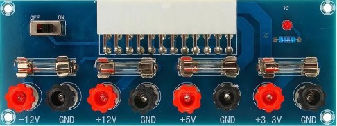
Pin Configuration and Descriptions

Pin/Output Description
+V Positive voltage output terminal
-V Negative voltage output terminal
GND Ground terminal
SET V Voltage setting control input
SET I Current setting control input
ON/OFF Power on/off switch

Usage Instructions

How to Use the Component in a Circuit

  1. Connect the Power Supply: Plug the bench power supply into an AC outlet.
  2. Set Voltage and Current: Before connecting your device, set the desired voltage and current limits using the control knobs or buttons.
  3. Connect the Device: Attach the positive lead from the power supply to the positive input of your device and the negative lead to the negative input or ground.
  4. Power On: Turn on the power supply. Monitor the voltage and current readings to ensure they match your requirements.
  5. Adjust as Needed: Fine-tune the voltage and current settings if necessary while observing the effect on your device.

Important Considerations and Best Practices

  • Start Low: Begin with lower voltage and current settings before gradually increasing to the desired levels.
  • Polarity Check: Ensure correct polarity when connecting the power supply to prevent damage.
  • Overload Protection: Utilize the current limit function to prevent overloading your circuit.
  • Cooling: Ensure proper ventilation around the power supply to prevent overheating.
  • Regular Calibration: Periodically calibrate the power supply to maintain accuracy.

Troubleshooting and FAQs

Common Issues Users Might Face

  • Inaccurate Voltage or Current: Check if the power supply needs calibration or if the measurement tools are accurate.
  • No Output: Ensure the power supply is turned on and the output terminals are properly connected.
  • Overheating: Reduce the load or improve ventilation around the power supply.

Solutions and Tips for Troubleshooting

  • Device Not Powering On: Verify that the power supply is on and the output settings are correct.
  • Unexpected Voltage Fluctuations: Check for loose connections and ensure the power supply is not overloaded.
  • Power Supply Shuts Down: This could be due to over-temperature or over-current protection. Allow it to cool down and check if the current limit is set too low.

FAQs

Q: Can I use a bench power supply to power multiple devices at once? A: Yes, as long as the total power requirements do not exceed the power supply's maximum output.

Q: How do I know if my power supply is calibrated correctly? A: Compare the power supply's readings with a known accurate multimeter. If there is a significant discrepancy, calibration may be needed.

Q: What should I do if the power supply is not responding to control adjustments? A: Turn off the power supply, unplug it, and check for any internal issues like a blown fuse or loose connections. If the problem persists, consult the manufacturer's support.

Note: Always refer to the manufacturer's manual for specific troubleshooting related to your model of bench power supply.