How to Use MDD10A Dual channel 10A DC Motor Driver: Examples, Pinouts, and Specs
Introduction
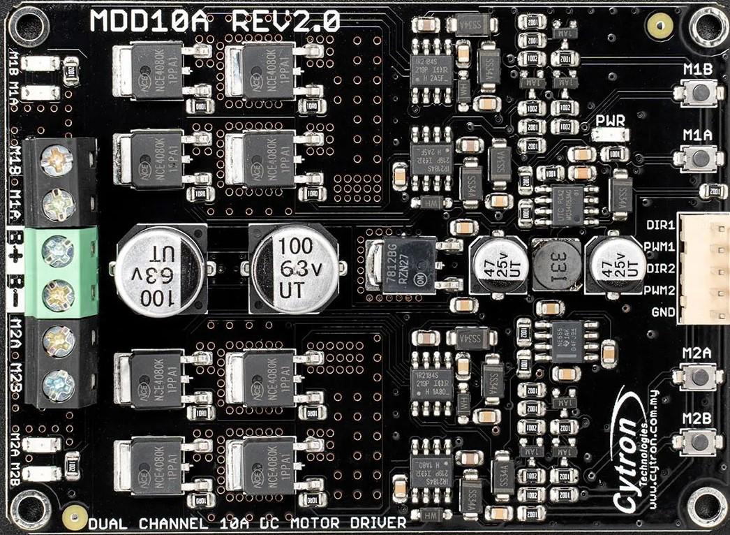
The MDD10A Dual Channel 10A DC Motor Driver (Manufacturer Part ID: MDD10A REV2.0) is a robust and versatile motor driver designed by Cytron. It is capable of controlling two DC motors simultaneously, with each channel supporting a maximum continuous current of 10A. The driver allows for bidirectional control and speed regulation, making it ideal for robotics, automation systems, and other motor control applications.
Explore Projects Built with MDD10A Dual channel 10A DC Motor Driver


Explore Projects Built with MDD10A Dual channel 10A DC Motor Driver
Common Applications
- Robotics (e.g., mobile robots, robotic arms)
- Automated conveyor systems
- Electric vehicles and carts
- DIY motorized projects
- Industrial motor control systems
Technical Specifications
Key Technical Details
- Input Voltage Range: 7V to 30V DC
- Maximum Continuous Current: 10A per channel
- Peak Current: 30A (for a few seconds)
- Control Signals:
- PWM (Pulse Width Modulation) for speed control
- Direction control via digital inputs
- PWM Frequency: Up to 20 kHz
- Logic Voltage: 3.3V or 5V compatible
- Thermal Protection: Built-in over-temperature shutdown
- Reverse Polarity Protection: Yes
- Dimensions: 84mm x 62mm x 25mm
- Weight: Approximately 80g
Pin Configuration and Descriptions
The MDD10A has two sets of input pins for motor control and two sets of output terminals for connecting motors. Below is the pin configuration:
Input Pins
| Pin Name | Description | Voltage Level |
|---|---|---|
| DIR1 | Direction control for Motor 1 | 0V (CW) / 5V (CCW) |
| PWM1 | Speed control for Motor 1 (PWM signal) | 0V to 5V |
| DIR2 | Direction control for Motor 2 | 0V (CW) / 5V (CCW) |
| PWM2 | Speed control for Motor 2 (PWM signal) | 0V to 5V |
| GND | Ground reference for control signals | 0V |
| VCC | Logic voltage input (3.3V or 5V) | 3.3V / 5V |
Output Terminals
| Terminal Name | Description |
|---|---|
| MOTOR1+ | Positive terminal for Motor 1 |
| MOTOR1- | Negative terminal for Motor 1 |
| MOTOR2+ | Positive terminal for Motor 2 |
| MOTOR2- | Negative terminal for Motor 2 |
Power Input Terminals
| Terminal Name | Description |
|---|---|
| VIN+ | Positive terminal for motor power supply |
| VIN- | Negative terminal for motor power supply |
Usage Instructions
How to Use the MDD10A in a Circuit
- Power Supply: Connect a DC power supply (7V to 30V) to the VIN+ and VIN- terminals. Ensure the power supply can handle the current requirements of your motors.
- Motor Connections: Connect the DC motors to the MOTOR1+/MOTOR1- and MOTOR2+/MOTOR2- terminals.
- Control Signals:
- Connect the DIR1, PWM1, DIR2, and PWM2 pins to a microcontroller (e.g., Arduino UNO) or other control circuitry.
- Use the VCC pin to provide the logic voltage (3.3V or 5V) and connect the GND pin to the ground of your control circuit.
- Direction Control: Set the DIR pins to HIGH or LOW to control the rotation direction of the motors.
- Speed Control: Provide a PWM signal (0% to 100% duty cycle) to the PWM pins to control motor speed.
Important Considerations and Best Practices
- Heat Dissipation: The MDD10A has built-in thermal protection, but for prolonged high-current operation, ensure proper ventilation or use a heat sink.
- Current Limitation: Avoid exceeding the 10A continuous current rating per channel to prevent damage.
- PWM Frequency: Use a PWM frequency of up to 20 kHz for optimal performance.
- Reverse Polarity: Ensure correct polarity when connecting the power supply to avoid damage.
Example: Connecting to an Arduino UNO
Below is an example of how to control two DC motors using the MDD10A and an Arduino UNO:
Circuit Diagram
- Connect DIR1, PWM1, DIR2, and PWM2 to Arduino digital pins (e.g., 7, 6, 5, and 4, respectively).
- Connect VCC to the Arduino's 5V pin and GND to the Arduino's GND pin.
- Connect the motors and power supply as described above.
Arduino Code
// Define control pins for Motor 1
const int dir1Pin = 7;  // Direction control for Motor 1
const int pwm1Pin = 6;  // Speed control (PWM) for Motor 1

// Define control pins for Motor 2
const int dir2Pin = 5;  // Direction control for Motor 2
const int pwm2Pin = 4;  // Speed control (PWM) for Motor 2

void setup() {
  // Set motor control pins as outputs
  pinMode(dir1Pin, OUTPUT);
  pinMode(pwm1Pin, OUTPUT);
  pinMode(dir2Pin, OUTPUT);
  pinMode(pwm2Pin, OUTPUT);
}

void loop() {
  // Example: Run Motor 1 forward at 50% speed
  digitalWrite(dir1Pin, HIGH);  // Set direction to forward
  analogWrite(pwm1Pin, 128);   // Set speed (128/255 = 50%)

  // Example: Run Motor 2 backward at 75% speed
  digitalWrite(dir2Pin, LOW);  // Set direction to backward
  analogWrite(pwm2Pin, 192);  // Set speed (192/255 = 75%)

  delay(5000);  // Run for 5 seconds

  // Stop both motors
  analogWrite(pwm1Pin, 0);  // Stop Motor 1
  analogWrite(pwm2Pin, 0);  // Stop Motor 2

  delay(2000);  // Wait for 2 seconds before repeating
}
Troubleshooting and FAQs
Common Issues and Solutions
Motors Not Running:
- Check the power supply voltage and ensure it is within the 7V to 30V range.
- Verify that the DIR and PWM signals are correctly connected and configured.
- Ensure the motors are properly connected to the output terminals.
Overheating:
- Ensure the current drawn by the motors does not exceed 10A per channel.
- Provide adequate ventilation or use a heat sink if operating at high currents.
No Response to PWM Signals:
- Confirm that the PWM frequency is within the supported range (up to 20 kHz).
- Check the logic voltage (VCC) and ensure it matches the control circuit (3.3V or 5V).
Motor Running in the Wrong Direction:
- Reverse the DIR pin signal (HIGH to LOW or LOW to HIGH) to change the motor direction.
FAQs
Can I use the MDD10A with a 3.3V microcontroller? Yes, the MDD10A is compatible with both 3.3V and 5V logic levels.
What happens if the current exceeds 10A? The MDD10A has built-in thermal protection and will shut down temporarily to prevent damage.
Can I control only one motor with the MDD10A? Yes, you can use just one channel if needed. Leave the unused channel unconnected.
Is the MDD10A suitable for stepper motors? No, the MDD10A is designed for DC motors and is not compatible with stepper motors.