Cirkit Designer Logo
Cirkit Designer
Your all-in-one circuit design IDE
Home / 
Component Documentation

How to Use IRLML2502 N-Channel MOSFET: Examples, Pinouts, and Specs

Image of IRLML2502 N-Channel MOSFET
Cirkit Designer LogoDesign with IRLML2502 N-Channel MOSFET in Cirkit Designer

Introduction

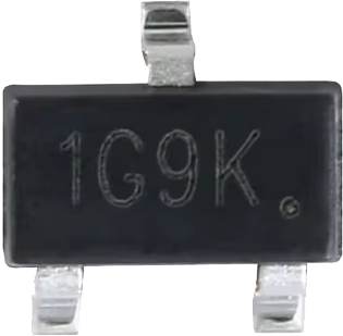
The IRLML2502 is a low-voltage N-channel MOSFET designed for high-speed switching applications. It features low on-resistance (RDS(on)) and fast switching times, making it ideal for power management and signal switching in various electronic circuits. Its compact SOT-23 package makes it suitable for space-constrained designs.

Explore Projects Built with IRLML2502 N-Channel MOSFET

Use Cirkit Designer to design, explore, and prototype these projects online. Some projects support real-time simulation. Click "Open Project" to start designing instantly!
Dual Motor Control Circuit with LED Indicator and Adjustable Speed
Image of Simple Drone: A project utilizing IRLML2502 N-Channel MOSFET in a practical application
This circuit is designed to control the speed and direction of coreless motors using MOSFETs, with a potentiometer providing adjustable speed control for one direction. A rocker switch enables power control, and a red LED serves as a power indicator. Diodes are included for motor back-EMF protection.
Cirkit Designer LogoOpen Project in Cirkit Designer
Pixhawk-Controlled Solenoid Driver with Voltage Regulation
Image of solenoid control circuit: A project utilizing IRLML2502 N-Channel MOSFET in a practical application
This circuit uses an LM393 comparator to drive an IRFZ44N MOSFET based on the comparison between two input signals from a pixhawk 2.4.8 flight controller. The MOSFET switches a solenoid, with a diode for back EMF protection, and the system is powered by a Lipo battery with voltage regulation provided by a step-up boost converter and a step-down voltage regulator to ensure stable operation. A resistor is connected to the gate of the MOSFET for proper biasing.
Cirkit Designer LogoOpen Project in Cirkit Designer
Battery-Powered LM393-Based Voltage Comparator Circuit with MOSFET Control
Image of cut off charger: A project utilizing IRLML2502 N-Channel MOSFET in a practical application
This circuit is a power regulation and control system that uses an LM393 comparator to monitor voltage levels and control a MOSFET (IRFZ44N) for switching. It is powered by a 12V battery and a USB power source, and includes various resistors and capacitors for filtering and stabilization.
Cirkit Designer LogoOpen Project in Cirkit Designer
ESP32-Controlled Pneumatic Solenoid Valve with MOSFET Switching
Image of ESPooky32: A project utilizing IRLML2502 N-Channel MOSFET in a practical application
This circuit uses an ESP32 microcontroller to control a 12V pneumatic solenoid valve via an IRFZ44N MOSFET as a switch. The ESP32 outputs a control signal through a 220-ohm resistor to the gate of the MOSFET, which in turn controls the power to the solenoid valve from a 12V power supply. A 10k-ohm resistor provides a pull-down for the MOSFET gate to ensure it remains off when not driven by the ESP32.
Cirkit Designer LogoOpen Project in Cirkit Designer

Explore Projects Built with IRLML2502 N-Channel MOSFET

Use Cirkit Designer to design, explore, and prototype these projects online. Some projects support real-time simulation. Click "Open Project" to start designing instantly!
Image of Simple Drone: A project utilizing IRLML2502 N-Channel MOSFET in a practical application
Dual Motor Control Circuit with LED Indicator and Adjustable Speed
This circuit is designed to control the speed and direction of coreless motors using MOSFETs, with a potentiometer providing adjustable speed control for one direction. A rocker switch enables power control, and a red LED serves as a power indicator. Diodes are included for motor back-EMF protection.
Cirkit Designer LogoOpen Project in Cirkit Designer
Image of solenoid control circuit: A project utilizing IRLML2502 N-Channel MOSFET in a practical application
Pixhawk-Controlled Solenoid Driver with Voltage Regulation
This circuit uses an LM393 comparator to drive an IRFZ44N MOSFET based on the comparison between two input signals from a pixhawk 2.4.8 flight controller. The MOSFET switches a solenoid, with a diode for back EMF protection, and the system is powered by a Lipo battery with voltage regulation provided by a step-up boost converter and a step-down voltage regulator to ensure stable operation. A resistor is connected to the gate of the MOSFET for proper biasing.
Cirkit Designer LogoOpen Project in Cirkit Designer
Image of cut off charger: A project utilizing IRLML2502 N-Channel MOSFET in a practical application
Battery-Powered LM393-Based Voltage Comparator Circuit with MOSFET Control
This circuit is a power regulation and control system that uses an LM393 comparator to monitor voltage levels and control a MOSFET (IRFZ44N) for switching. It is powered by a 12V battery and a USB power source, and includes various resistors and capacitors for filtering and stabilization.
Cirkit Designer LogoOpen Project in Cirkit Designer
Image of ESPooky32: A project utilizing IRLML2502 N-Channel MOSFET in a practical application
ESP32-Controlled Pneumatic Solenoid Valve with MOSFET Switching
This circuit uses an ESP32 microcontroller to control a 12V pneumatic solenoid valve via an IRFZ44N MOSFET as a switch. The ESP32 outputs a control signal through a 220-ohm resistor to the gate of the MOSFET, which in turn controls the power to the solenoid valve from a 12V power supply. A 10k-ohm resistor provides a pull-down for the MOSFET gate to ensure it remains off when not driven by the ESP32.
Cirkit Designer LogoOpen Project in Cirkit Designer

Common Applications

  • DC-DC converters
  • Load switching in battery-powered devices
  • Signal switching in microcontroller-based circuits
  • Motor drivers for small motors
  • LED drivers

Technical Specifications

Key Specifications

Parameter Value
Drain-Source Voltage (VDS) 20V
Gate-Source Voltage (VGS) ±8V
Continuous Drain Current (ID) 3.4A (at VGS = 4.5V, TA = 25°C)
Pulsed Drain Current (IDM) 12A
Power Dissipation (PD) 1.25W (TA = 25°C)
RDS(on) (at VGS = 4.5V) 0.028Ω
RDS(on) (at VGS = 2.5V) 0.035Ω
Operating Temperature Range -55°C to +150°C
Package Type SOT-23

Pin Configuration

The IRLML2502 is housed in a 3-pin SOT-23 package. The pinout is as follows:

Pin Number Pin Name Description
1 Gate Controls the MOSFET switching
2 Source Connected to ground or load
3 Drain Connected to the load or power

Usage Instructions

How to Use the IRLML2502 in a Circuit

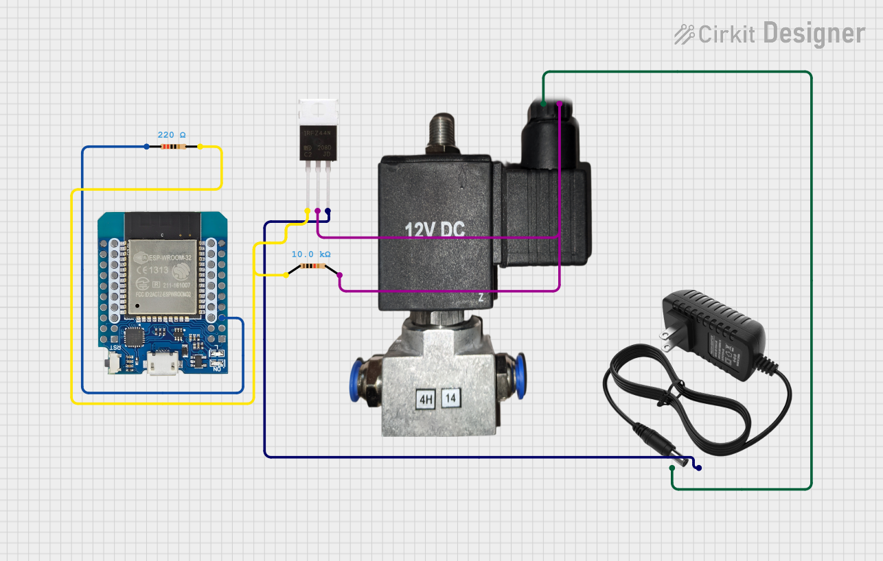
  1. Gate Control: Connect the Gate pin to a control signal (e.g., from a microcontroller or logic circuit). Ensure the control voltage is within the specified VGS range (0V to 8V).
  2. Drain-Source Path: Connect the Drain pin to the load and the Source pin to ground (for low-side switching) or to the power supply (for high-side switching).
  3. Gate Resistor: Use a resistor (typically 10Ω to 100Ω) in series with the Gate to limit inrush current and prevent damage to the MOSFET.
  4. Flyback Diode: For inductive loads (e.g., motors or relays), add a flyback diode across the load to protect the MOSFET from voltage spikes.

Example Circuit

Below is an example of using the IRLML2502 to control an LED with an Arduino UNO:

Circuit Description

  • The IRLML2502 acts as a low-side switch for the LED.
  • The Gate is connected to a digital pin on the Arduino.
  • A 220Ω resistor limits the current through the LED.

Arduino Code

// Define the pin connected to the MOSFET Gate
const int mosfetGatePin = 9;

void setup() {
  pinMode(mosfetGatePin, OUTPUT); // Set the MOSFET Gate pin as an output
}

void loop() {
  digitalWrite(mosfetGatePin, HIGH); // Turn on the MOSFET (LED ON)
  delay(1000);                       // Wait for 1 second
  digitalWrite(mosfetGatePin, LOW);  // Turn off the MOSFET (LED OFF)
  delay(1000);                       // Wait for 1 second
}

Important Considerations

  • Gate Drive Voltage: Ensure the Gate voltage is sufficient to fully turn on the MOSFET. For optimal performance, use a VGS of 4.5V or higher.
  • Thermal Management: If operating near the maximum current rating, ensure proper heat dissipation (e.g., using a PCB with adequate copper area).
  • Load Type: For inductive loads, always use a flyback diode to protect the MOSFET from voltage spikes.

Troubleshooting and FAQs

Common Issues and Solutions

  1. MOSFET Not Switching Properly

    • Cause: Insufficient Gate voltage.
    • Solution: Ensure the Gate voltage is at least 4.5V for full enhancement.
  2. Excessive Heat Generation

    • Cause: High current or inadequate heat dissipation.
    • Solution: Check the current through the MOSFET and improve thermal management.
  3. MOSFET Fails or Shorts

    • Cause: Voltage spikes from inductive loads.
    • Solution: Add a flyback diode across the load.
  4. Low Efficiency

    • Cause: High RDS(on) due to low Gate voltage.
    • Solution: Use a Gate voltage closer to 4.5V or higher.

FAQs

Q1: Can the IRLML2502 be used with 3.3V logic?
A1: Yes, the IRLML2502 can operate with 3.3V logic, but ensure the load current and RDS(on) are within acceptable limits.

Q2: Is the IRLML2502 suitable for high-side switching?
A2: Yes, but you may need a Gate driver circuit to ensure proper Gate voltage relative to the Source.

Q3: Can I use the IRLML2502 for PWM applications?
A3: Yes, the IRLML2502 is suitable for PWM due to its fast switching characteristics.

Q4: What is the maximum load current I can drive?
A4: The maximum continuous current is 3.4A at 25°C, but consider thermal limitations and ensure proper heat dissipation.