How to Use PowerBoost 1000 Basic Terminal USB: Examples, Pinouts, and Specs
Introduction
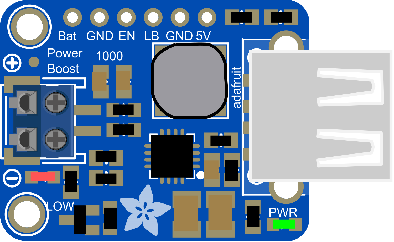
The PowerBoost 1000 Basic is a versatile power supply module designed to boost input voltage to a stable 5V output, which can be accessed via a USB port. This makes it ideal for portable electronics, DIY projects, and any application requiring a 5V USB power supply. It is particularly useful for charging USB devices or powering projects that require a USB connection.
Explore Projects Built with PowerBoost 1000 Basic Terminal USB

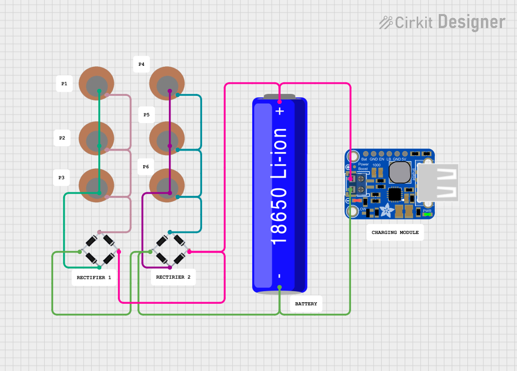

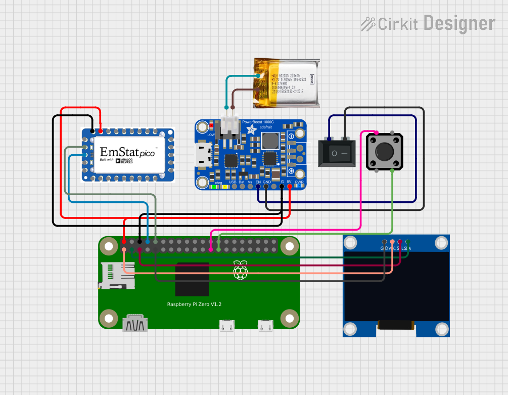
Explore Projects Built with PowerBoost 1000 Basic Terminal USB
Common Applications and Use Cases
- Portable USB chargers
- Battery-powered electronics
- DIY USB power supplies for Raspberry Pi, Arduino, and other microcontrollers
- Wearable electronics
- Mobile robotics
Technical Specifications
Key Technical Details
- Input Voltage: 1.8V to 5.5V DC
- Output Voltage: 5V DC
- Maximum Output Current: 1A
- Efficiency: 90% typical at 3.7V IN to 5V OUT at 500mA
- Quiescent Current: 5mA typical
Pin Configuration and Descriptions
| Pin Name | Description |
|---|---|
| VIN | Input voltage (1.8V to 5.5V DC) |
| GND | Ground connection |
| USB A | USB output connector |
| EN | Enable pin (active high) |
| BAT | Battery connection for rechargeable batteries |
| 5V | Regulated 5V output |
Usage Instructions
How to Use the Component in a Circuit
Connecting Power Source:
- Connect your power source to the VIN and GND pins. Ensure that the voltage is within the specified range (1.8V to 5.5V DC).
Enabling the Module:
- The EN pin can be left disconnected if you want the module to be always on. To control power, connect the EN pin to a digital output on a microcontroller and set it high to enable.
Connecting a Load:
- Connect your USB device to the USB A port for charging or powering. Alternatively, use the 5V and GND pins to power a circuit that requires a regulated 5V supply.
Important Considerations and Best Practices
- Do not exceed the recommended input voltage range to prevent damage.
- Ensure that the total current draw from the USB port does not exceed 1A.
- If using the EN pin, ensure that the voltage applied is compatible with the logic level of the PowerBoost 1000 Basic.
- For battery-powered applications, make sure to use rechargeable batteries compatible with the BAT pin specifications.
Troubleshooting and FAQs
Common Issues
- Device not powering on: Check the input voltage and connections to VIN and GND. Ensure the EN pin is set high if used.
- Insufficient power to the device: Ensure that the power source can supply enough current and that the device's current draw does not exceed 1A.
Solutions and Tips for Troubleshooting
- Verify all connections are secure and correct.
- Measure the input voltage to ensure it falls within the specified range.
- If using the EN pin, check the control signal with a multimeter or oscilloscope to ensure it is functioning correctly.
FAQs
Q: Can I use the PowerBoost 1000 Basic to charge my smartphone? A: Yes, as long as the smartphone charges via USB and requires 5V, and the current draw is within 1A.
Q: What should I do if my device is drawing more than 1A? A: You should use a different power module that can handle higher currents. Exceeding the current limit can damage the PowerBoost 1000 Basic.
Q: Can I use multiple PowerBoost 1000 Basics to increase the current output? A: It is not recommended to parallel the outputs of multiple PowerBoost modules to increase current capacity, as this can lead to uneven loading and potential damage.
Example Code for Arduino UNO
// Example code to control PowerBoost 1000 Basic with Arduino UNO
const int enablePin = 2; // Connect to the EN pin on PowerBoost

void setup() {
  pinMode(enablePin, OUTPUT);
  // Start with the PowerBoost disabled
  digitalWrite(enablePin, LOW);
}

void loop() {
  // Enable the PowerBoost for 10 seconds
  digitalWrite(enablePin, HIGH);
  delay(10000);
  // Disable the PowerBoost
  digitalWrite(enablePin, LOW);
  delay(10000);
}
Note: This example assumes that the PowerBoost 1000 Basic's EN pin is connected to digital pin 2 on the Arduino UNO. The code toggles the power supply every 10 seconds. Adjust the delay values as needed for your application.