How to Use deneyap mini: Examples, Pinouts, and Specs
Introduction
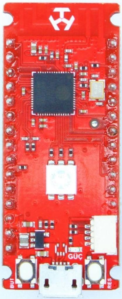
The Deneyap Mini is a compact microcontroller board designed for educational purposes, making it an excellent choice for students, hobbyists, and developers. It features a variety of input/output pins, built-in sensors, and compatibility with popular programming environments such as Arduino IDE and MicroPython. The board is tailored to facilitate hands-on learning in electronics, programming, and IoT applications.
Explore Projects Built with deneyap mini


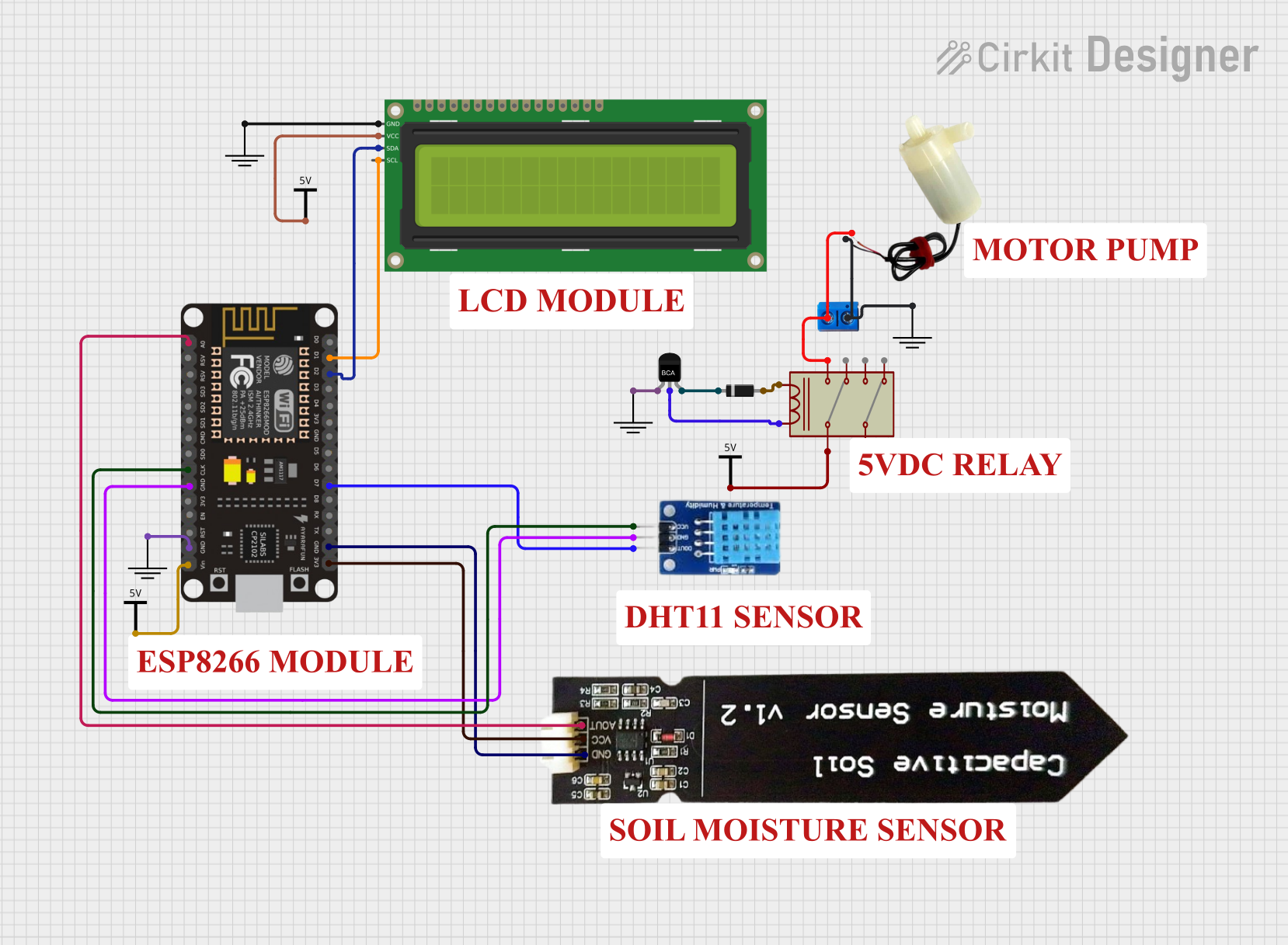
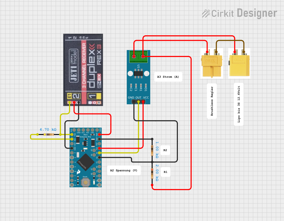
Explore Projects Built with deneyap mini
Common Applications and Use Cases
- Prototyping IoT devices and smart systems
- Educational projects in electronics and programming
- Sensor-based data collection and analysis
- Robotics and automation projects
- Wearable technology development
Technical Specifications
The Deneyap Mini is equipped with robust hardware features that make it versatile for a wide range of applications. Below are its key technical details:
Key Technical Details
- Microcontroller: ESP32-based dual-core processor
- Operating Voltage: 3.3V
- Input Voltage: 5V (via USB) or 3.7V (via LiPo battery)
- Digital I/O Pins: 20 (including PWM support)
- Analog Input Pins: 6 (12-bit ADC resolution)
- Communication Protocols: UART, I2C, SPI
- Built-in Sensors: Accelerometer, gyroscope, and temperature sensor
- Wireless Connectivity: Wi-Fi (802.11 b/g/n) and Bluetooth 4.2
- Programming Environments: Arduino IDE, MicroPython, and PlatformIO
- Dimensions: 30mm x 55mm
Pin Configuration and Descriptions
The Deneyap Mini features a variety of pins for interfacing with external components. Below is the pin configuration:
| Pin Name | Type | Description |
|---|---|---|
| VIN | Power Input | Input voltage (5V via USB or 3.7V via LiPo battery). |
| GND | Ground | Common ground for the circuit. |
| 3V3 | Power Output | 3.3V regulated output for powering external components. |
| GPIO0-GPIO19 | Digital I/O | General-purpose digital input/output pins (some support PWM). |
| ADC0-ADC5 | Analog Input | Analog input pins with 12-bit resolution. |
| TX, RX | UART | Serial communication pins for UART (TX: Transmit, RX: Receive). |
| SCL, SDA | I2C | I2C communication pins (SCL: Clock, SDA: Data). |
| MOSI, MISO, SCK | SPI | SPI communication pins (MOSI: Master Out Slave In, MISO: Master In Slave Out, SCK: Clock). |
| RST | Reset | Resets the microcontroller. |
Usage Instructions
The Deneyap Mini is easy to use and can be programmed using the Arduino IDE or MicroPython. Below are the steps to get started and some best practices for using the board.
How to Use the Deneyap Mini in a Circuit
Powering the Board:
- Connect the board to your computer via a USB cable for programming and power.
- Alternatively, use a 3.7V LiPo battery for portable applications.
Programming the Board:
- Install the Arduino IDE and add the ESP32 board package.
- Select "Deneyap Mini" from the board manager.
- Write your code and upload it to the board via the USB connection.
Connecting Components:
- Use the GPIO pins for digital input/output operations.
- Connect sensors to the ADC pins for analog input.
- Use the I2C or SPI pins for communication with external modules.
Using Built-in Sensors:
- Access the accelerometer, gyroscope, and temperature sensor using the appropriate libraries.
Important Considerations and Best Practices
- Always ensure the input voltage does not exceed the specified limits to avoid damaging the board.
- Use pull-up or pull-down resistors for GPIO pins when necessary.
- Avoid drawing excessive current from the 3.3V output pin.
- Use proper decoupling capacitors when connecting external components to reduce noise.
Example Code for Arduino IDE
Below is an example code to read the built-in temperature sensor and print the value to the Serial Monitor:
// Include the necessary library for the Deneyap Mini
#include <Wire.h>

// Define the I2C address for the temperature sensor
#define TEMP_SENSOR_ADDR 0x48

void setup() {
  Serial.begin(115200); // Initialize serial communication at 115200 baud
  Wire.begin();         // Initialize I2C communication
  Serial.println("Temperature Sensor Example");
}

void loop() {
  Wire.beginTransmission(TEMP_SENSOR_ADDR); // Start communication with sensor
  Wire.write(0x00);                         // Request temperature data
  Wire.endTransmission();

  Wire.requestFrom(TEMP_SENSOR_ADDR, 2);    // Request 2 bytes of data
  if (Wire.available() == 2) {
    int tempRaw = (Wire.read() << 8) | Wire.read(); // Combine two bytes
    float temperature = tempRaw * 0.0625;          // Convert to Celsius
    Serial.print("Temperature: ");
    Serial.print(temperature);
    Serial.println(" °C");
  }

  delay(1000); // Wait 1 second before the next reading
}
Troubleshooting and FAQs
Common Issues and Solutions
The board is not detected by the computer:
- Ensure the USB cable is properly connected and supports data transfer.
- Install the correct USB driver for the Deneyap Mini.
Code upload fails:
- Check that the correct board and port are selected in the Arduino IDE.
- Press and hold the reset button while uploading the code.
Sensors are not providing data:
- Verify the connections and ensure the correct I2C address is used.
- Check for any library dependencies and install them in the Arduino IDE.
Wi-Fi or Bluetooth is not working:
- Ensure the correct credentials or pairing settings are used.
- Check for interference from other devices or networks.
FAQs
Can I power the Deneyap Mini with a battery?
Yes, you can use a 3.7V LiPo battery connected to the VIN and GND pins.What programming languages are supported?
The Deneyap Mini supports Arduino IDE (C/C++) and MicroPython.How do I reset the board?
Press the RST button on the board to perform a hardware reset.Can I use the Deneyap Mini for IoT projects?
Absolutely! The built-in Wi-Fi and Bluetooth make it ideal for IoT applications.
This concludes the documentation for the Deneyap Mini. Happy tinkering!