How to Use AEM10941 Evaluation Board: Examples, Pinouts, and Specs
Introduction
The AEM10941 Evaluation Board is a development platform designed to evaluate the performance of the AEM10941 energy harvesting power management IC from e-peas. This board enables users to test and optimize energy harvesting applications by providing a convenient interface for connecting energy sources, storage elements, and loads. The AEM10941 IC is specifically designed to extract energy from low-power sources such as photovoltaic cells, thermoelectric generators, or piezoelectric elements, and efficiently manage the harvested energy for powering low-power devices.
Explore Projects Built with AEM10941 Evaluation Board


Explore Projects Built with AEM10941 Evaluation Board
Common Applications and Use Cases
- IoT devices powered by energy harvesting
- Wearable electronics
- Wireless sensor networks
- Remote monitoring systems
- Battery-free or extended-lifetime devices
Technical Specifications
Key Technical Details
- Input Voltage Range: 50 mV to 5 V
- Cold Start Voltage: 380 mV (minimum input voltage required to start operation)
- Input Power Range: Up to 50 mW
- Output Voltage Options:
- Configurable primary output: 1.8 V, 2.5 V, 3.3 V, or 4.1 V
- Secondary output: 1.8 V (fixed)
- Quiescent Current: Ultra-low, enabling efficient energy harvesting
- Energy Storage: Supports supercapacitors or rechargeable batteries
- Operating Temperature Range: -40°C to +125°C
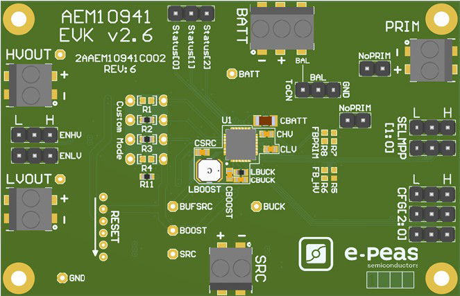
Pin Configuration and Descriptions
The AEM10941 Evaluation Board features several connectors and test points for easy integration and testing. Below is a table describing the key pins and connectors:
| Pin/Connector | Description |
|---|---|
| VIN | Input voltage from the energy harvesting source (e.g., solar panel, TEG). |
| VOUT1 | Configurable primary output voltage for powering the load. |
| VOUT2 | Fixed 1.8 V secondary output for low-power devices. |
| VBAT | Connection for the energy storage element (e.g., supercapacitor or battery). |
| GND | Ground connection. |
| JP1, JP2 | Jumpers for configuring the primary output voltage (1.8 V, 2.5 V, 3.3 V, 4.1 V). |
| Test Points | Multiple test points for monitoring voltages and currents at various stages. |
Usage Instructions
How to Use the Component in a Circuit
- Connect the Energy Source: Attach your energy harvesting source (e.g., a solar panel or TEG) to the
VINconnector. Ensure the source voltage is within the supported range (50 mV to 5 V). - Connect the Energy Storage Element: Attach a supercapacitor or rechargeable battery to the
VBATconnector. This will store the harvested energy. - Configure the Output Voltage: Use the jumpers (JP1 and JP2) to set the desired primary output voltage (1.8 V, 2.5 V, 3.3 V, or 4.1 V).
- Connect the Load: Attach your load to the
VOUT1and/orVOUT2connectors. Ensure the load's power requirements are within the board's capabilities. - Monitor Performance: Use the test points to measure voltages and currents at various stages of the circuit for evaluation and optimization.
Important Considerations and Best Practices
- Cold Start Requirements: Ensure the input source can provide at least 380 mV to initiate operation. Once started, the board can operate with input voltages as low as 50 mV.
- Energy Storage Selection: Choose an energy storage element with appropriate capacity and voltage ratings for your application. Supercapacitors are ideal for short-term storage, while rechargeable batteries are better for long-term use.
- Load Matching: Ensure the connected load does not exceed the output power capabilities of the board.
- Environmental Conditions: Operate the board within the specified temperature range (-40°C to +125°C) for optimal performance.
Example Code for Arduino UNO Integration
The AEM10941 Evaluation Board can be used to power an Arduino UNO in low-power applications. Below is an example code snippet to read a sensor value and transmit it via serial communication:
// Example: Reading a sensor value and transmitting via serial
// Ensure the AEM10941 Evaluation Board is configured to provide 3.3V or 5V
// to power the Arduino UNO.

const int sensorPin = A0; // Analog pin connected to the sensor
int sensorValue = 0;      // Variable to store the sensor reading

void setup() {
  Serial.begin(9600); // Initialize serial communication at 9600 baud
  pinMode(sensorPin, INPUT); // Set the sensor pin as input
}

void loop() {
  sensorValue = analogRead(sensorPin); // Read the sensor value
  Serial.print("Sensor Value: ");      // Print label to serial monitor
  Serial.println(sensorValue);         // Print the sensor value
  delay(1000); // Wait for 1 second before the next reading
}
Troubleshooting and FAQs
Common Issues and Solutions
The board does not start operating.
- Cause: The input voltage is below the cold start threshold (380 mV).
- Solution: Ensure the energy source provides at least 380 mV to initiate operation.
Output voltage is not as expected.
- Cause: Incorrect jumper configuration for the primary output voltage.
- Solution: Verify the positions of JP1 and JP2 and set them according to the desired output voltage.
The load is not powered.
- Cause: Insufficient energy stored in the supercapacitor or battery.
- Solution: Allow more time for the energy storage element to charge before connecting the load.
The board overheats during operation.
- Cause: Excessive input power or load current.
- Solution: Ensure the input power and load current are within the board's specifications.
FAQs
Can I use a non-rechargeable battery with the AEM10941 Evaluation Board?
- No, the board is designed to work with rechargeable batteries or supercapacitors only.
What is the maximum power the board can handle?
- The board can handle input power up to 50 mW.
Can I use the board in outdoor environments?
- Yes, but ensure the board is protected from moisture and extreme conditions beyond its operating temperature range.
How do I monitor the energy harvesting performance?
- Use the test points on the board to measure input/output voltages and currents with a multimeter or oscilloscope.