How to Use DOB LED: Examples, Pinouts, and Specs
Introduction
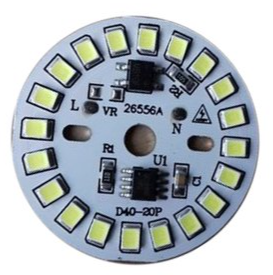
A DOB (Driver on Board) LED is an integrated lighting solution that combines the LED chip and driver circuitry into a single package. This design eliminates the need for an external driver, making it a compact and efficient solution for various lighting applications. DOB LEDs are widely used in residential, commercial, and industrial lighting due to their simplicity, cost-effectiveness, and ease of installation.
Explore Projects Built with DOB LED
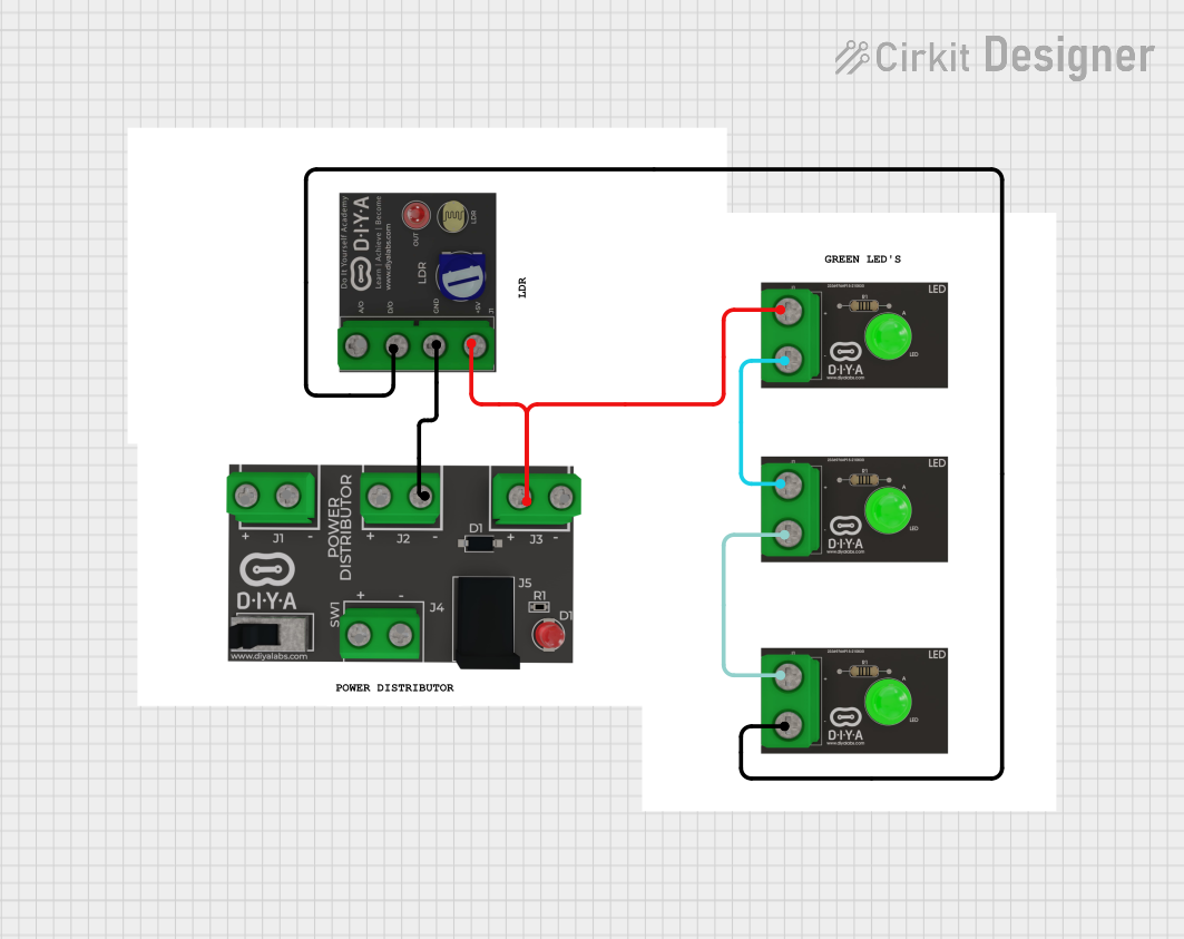
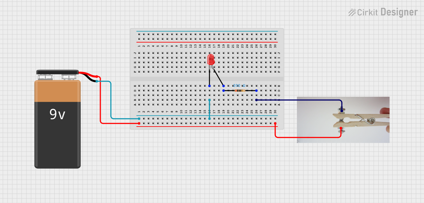
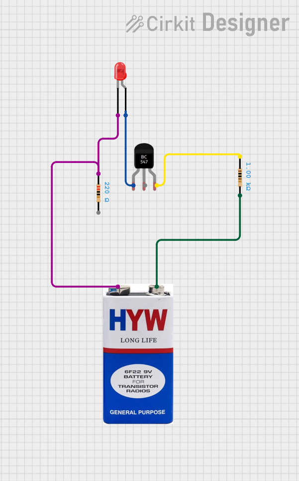
Explore Projects Built with DOB LED
Common Applications and Use Cases
- Indoor and outdoor lighting fixtures
- LED bulbs and tube lights
- Streetlights and floodlights
- Decorative and architectural lighting
- Emergency lighting systems
Technical Specifications
Below are the general technical specifications for a typical DOB LED. Note that specific values may vary depending on the manufacturer and model.
Key Technical Details
- Input Voltage: 110V AC or 220V AC (depending on the model)
- Power Rating: 3W to 50W (varies by application)
- Luminous Efficacy: 80-120 lumens per watt
- Color Temperature: 2700K to 6500K (warm white to cool white)
- Power Factor: ≥ 0.9
- Operating Temperature: -20°C to 50°C
- Lifespan: 25,000 to 50,000 hours
Pin Configuration and Descriptions
DOB LEDs typically have two input terminals for AC power and may include additional pads for mounting or heat dissipation. Below is a general pin configuration:
| Pin Name | Description |
|---|---|
| AC Input (+) | Positive AC input terminal |
| AC Input (-) | Negative AC input terminal |
| NC (if any) | No connection (used for mechanical support) |
Usage Instructions
How to Use the Component in a Circuit
- Power Supply: Connect the AC input terminals of the DOB LED directly to the AC mains supply (110V or 220V, depending on the model). Ensure the voltage matches the specifications of the LED.
- Mounting: Secure the DOB LED to a heat sink or a thermally conductive surface to ensure proper heat dissipation and prevent overheating.
- Polarity: While the AC input terminals are not polarized, ensure proper wiring to avoid short circuits or damage.
- Insulation: Use proper insulation and enclosures to protect the LED and users from electrical hazards.
Important Considerations and Best Practices
- Heat Management: Always use a heat sink or thermal paste to manage heat effectively, as excessive heat can reduce the lifespan of the LED.
- Surge Protection: Install surge protection devices to safeguard the LED from voltage spikes.
- Dimming: If dimming is required, ensure the DOB LED is compatible with dimmer switches or circuits.
- Safety: Avoid direct contact with the AC terminals during operation to prevent electric shock.
Example: Connecting a DOB LED to an Arduino UNO
While DOB LEDs are designed for direct AC operation, they are not typically controlled by microcontrollers like the Arduino UNO. However, if you wish to control the power to a DOB LED using an Arduino, you can use a relay module. Below is an example:
/*
  Example: Controlling a DOB LED with an Arduino UNO and a relay module
  This code turns the DOB LED on and off at 1-second intervals.
*/

const int relayPin = 7; // Pin connected to the relay module

void setup() {
  pinMode(relayPin, OUTPUT); // Set the relay pin as an output
}

void loop() {
  digitalWrite(relayPin, HIGH); // Turn the relay (and LED) ON
  delay(1000);                 // Wait for 1 second
  digitalWrite(relayPin, LOW); // Turn the relay (and LED) OFF
  delay(1000);                 // Wait for 1 second
}
Note: Ensure the relay module is rated for the AC voltage and current of the DOB LED.
Troubleshooting and FAQs
Common Issues and Solutions
LED Does Not Light Up
- Cause: Incorrect wiring or insufficient input voltage.
- Solution: Verify the wiring and ensure the input voltage matches the LED's specifications.
Flickering Light
- Cause: Poor power quality or a faulty driver circuit.
- Solution: Use a voltage stabilizer or replace the DOB LED if the driver is damaged.
Overheating
- Cause: Inadequate heat dissipation.
- Solution: Attach the LED to a proper heat sink and ensure good airflow.
Short Lifespan
- Cause: Operating the LED beyond its rated voltage or temperature.
- Solution: Ensure the LED is used within its specified limits and install surge protection.
FAQs
Q: Can I use a DOB LED with a DC power supply?
A: No, DOB LEDs are designed for AC operation and require an AC input to function.Q: Are DOB LEDs dimmable?
A: Some DOB LEDs are dimmable, but you must check the manufacturer's specifications to confirm compatibility with dimmer switches.Q: How do I extend the lifespan of a DOB LED?
A: Ensure proper heat dissipation, use surge protection, and operate the LED within its rated voltage and temperature range.Q: Can I repair a faulty DOB LED?
A: While it is possible to repair the driver circuit, it is often more practical to replace the entire unit due to the compact design.
This concludes the documentation for the DOB LED.