Cirkit Designer Logo
Cirkit Designer
Your all-in-one circuit design IDE
Home / 
Component Documentation

How to Use buzzer: Examples, Pinouts, and Specs

Image of buzzer
Cirkit Designer LogoDesign with buzzer in Cirkit Designer

Introduction

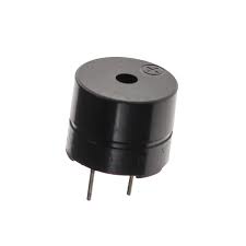
A buzzer is an audio signaling device that produces a buzzing sound, often used for alarms, timers, and user feedback in electronic circuits. Buzzers are commonly found in various applications such as household appliances, automotive systems, and electronic gadgets. They are valued for their simplicity, reliability, and ease of integration into circuits.

Explore Projects Built with buzzer

Use Cirkit Designer to design, explore, and prototype these projects online. Some projects support real-time simulation. Click "Open Project" to start designing instantly!
Battery-Powered IR Sensor with Buzzer Alert System
Image of fire detector: A project utilizing buzzer in a practical application
This circuit is a sensor-activated buzzer system powered by a battery. An IR sensor detects an object and triggers an NPN transistor, which in turn activates a relay to power a buzzer. The circuit includes a voltage regulator to ensure stable 5V power supply and a rocker switch for manual control.
Cirkit Designer LogoOpen Project in Cirkit Designer
Battery-Powered IR Sensor and Buzzer Alarm System
Image of blindstick: A project utilizing buzzer in a practical application
This circuit consists of an IR sensor and a buzzer powered by a 9V battery. The IR sensor detects an object and triggers the buzzer to sound an alarm when an object is detected.
Cirkit Designer LogoOpen Project in Cirkit Designer
Arduino UNO Controlled School Bell System with DS3231 RTC and Relay Module
Image of automatic bell system: A project utilizing buzzer in a practical application
This circuit is designed as an automatic school bell system controlled by an Arduino UNO microcontroller. The Arduino is programmed to ring a buzzer at the start of each school period, with a total of 6 periods defined in the code. The DS3231 Real-Time Clock (RTC) module is used for accurate timekeeping, and a relay module interfaces the Arduino with the buzzer to handle the higher current required to drive the buzzer.
Cirkit Designer LogoOpen Project in Cirkit Designer
Battery-Powered IR Sensor with Buzzer Alert System
Image of Counter Tally: A project utilizing buzzer in a practical application
This circuit uses an IR sensor to detect an object and activate a buzzer. The IR sensor is powered by a 9V battery, and its output is connected to the positive terminal of the buzzer, causing the buzzer to sound when an object is detected.
Cirkit Designer LogoOpen Project in Cirkit Designer

Explore Projects Built with buzzer

Use Cirkit Designer to design, explore, and prototype these projects online. Some projects support real-time simulation. Click "Open Project" to start designing instantly!
Image of fire detector: A project utilizing buzzer in a practical application
Battery-Powered IR Sensor with Buzzer Alert System
This circuit is a sensor-activated buzzer system powered by a battery. An IR sensor detects an object and triggers an NPN transistor, which in turn activates a relay to power a buzzer. The circuit includes a voltage regulator to ensure stable 5V power supply and a rocker switch for manual control.
Cirkit Designer LogoOpen Project in Cirkit Designer
Image of blindstick: A project utilizing buzzer in a practical application
Battery-Powered IR Sensor and Buzzer Alarm System
This circuit consists of an IR sensor and a buzzer powered by a 9V battery. The IR sensor detects an object and triggers the buzzer to sound an alarm when an object is detected.
Cirkit Designer LogoOpen Project in Cirkit Designer
Image of automatic bell system: A project utilizing buzzer in a practical application
Arduino UNO Controlled School Bell System with DS3231 RTC and Relay Module
This circuit is designed as an automatic school bell system controlled by an Arduino UNO microcontroller. The Arduino is programmed to ring a buzzer at the start of each school period, with a total of 6 periods defined in the code. The DS3231 Real-Time Clock (RTC) module is used for accurate timekeeping, and a relay module interfaces the Arduino with the buzzer to handle the higher current required to drive the buzzer.
Cirkit Designer LogoOpen Project in Cirkit Designer
Image of Counter Tally: A project utilizing buzzer in a practical application
Battery-Powered IR Sensor with Buzzer Alert System
This circuit uses an IR sensor to detect an object and activate a buzzer. The IR sensor is powered by a 9V battery, and its output is connected to the positive terminal of the buzzer, causing the buzzer to sound when an object is detected.
Cirkit Designer LogoOpen Project in Cirkit Designer

Technical Specifications

Key Technical Details

Parameter Value
Operating Voltage 3V to 12V
Current Consumption 10mA to 30mA
Sound Output 85dB at 10cm
Frequency Range 2kHz to 4kHz
Operating Temperature -20°C to +60°C
Dimensions Varies (commonly 12mm diameter)

Pin Configuration and Descriptions

Pin Number Pin Name Description
1 VCC Positive supply voltage (3V to 12V)
2 GND Ground (0V)

Usage Instructions

How to Use the Buzzer in a Circuit

  1. Power Supply: Connect the VCC pin of the buzzer to the positive terminal of the power supply (3V to 12V). Connect the GND pin to the ground terminal of the power supply.
  2. Control Signal: To control the buzzer, you can use a microcontroller (e.g., Arduino) or a simple switch. When the control signal is applied, the buzzer will produce a sound.

Important Considerations and Best Practices

  • Voltage Range: Ensure that the supply voltage is within the specified range (3V to 12V) to avoid damaging the buzzer.
  • Current Limiting: Use a current-limiting resistor if necessary to prevent excessive current flow.
  • Mounting: Secure the buzzer properly in your circuit to avoid mechanical vibrations that could affect performance.
  • Polarity: Observe correct polarity when connecting the buzzer to the power supply.

Example Circuit with Arduino UNO

/*
  Example code to control a buzzer with Arduino UNO.
  The buzzer will beep on and off every second.
*/

const int buzzerPin = 8; // Pin connected to the buzzer

void setup() {
  pinMode(buzzerPin, OUTPUT); // Set the buzzer pin as an output
}

void loop() {
  digitalWrite(buzzerPin, HIGH); // Turn the buzzer on
  delay(1000);                   // Wait for 1 second
  digitalWrite(buzzerPin, LOW);  // Turn the buzzer off
  delay(1000);                   // Wait for 1 second
}

Troubleshooting and FAQs

Common Issues Users Might Face

  1. No Sound from Buzzer:

    • Solution: Check the power supply connections and ensure the voltage is within the specified range. Verify that the control signal is being applied correctly.
  2. Buzzer Produces Weak Sound:

    • Solution: Ensure that the supply voltage is adequate. Check for any loose connections or poor solder joints.
  3. Buzzer is Always On:

    • Solution: Verify the control signal logic. Ensure that the microcontroller or switch is functioning correctly.

FAQs

Q1: Can I use the buzzer with a 5V power supply?

  • A1: Yes, the buzzer can operate within a voltage range of 3V to 12V, so a 5V power supply is suitable.

Q2: How can I change the sound frequency of the buzzer?

  • A2: The sound frequency of a passive buzzer can be controlled by varying the frequency of the control signal. For an active buzzer, the frequency is fixed.

Q3: Is it necessary to use a current-limiting resistor with the buzzer?

  • A3: It depends on the current rating of your power supply and the buzzer. If the current exceeds the buzzer's rating, a current-limiting resistor is recommended.

By following this documentation, users can effectively integrate and troubleshoot buzzers in their electronic projects, ensuring reliable and efficient operation.