How to Use RC Reciever 6 channels: Examples, Pinouts, and Specs
Introduction
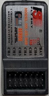
The FlySky FS-R6B is a 6-channel 2.4GHz radio control receiver designed to work with FlySky transmitter modules. It is commonly used in remote-controlled (RC) vehicles, drones, and aircraft to receive commands from a remote transmitter. Each of the six channels can be used to control a different function, such as throttle, rudder, ailerons, elevators, etc.
Explore Projects Built with RC Reciever 6 channels
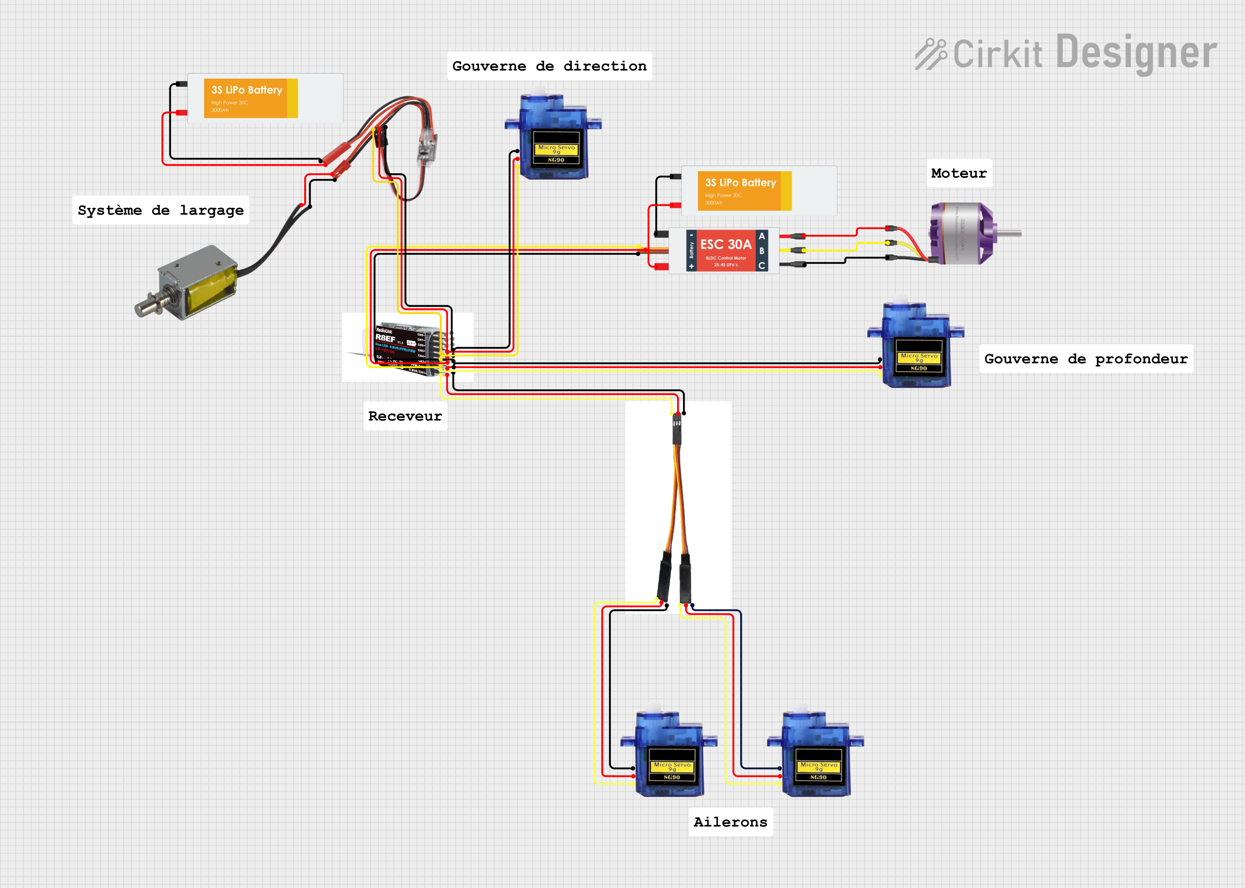
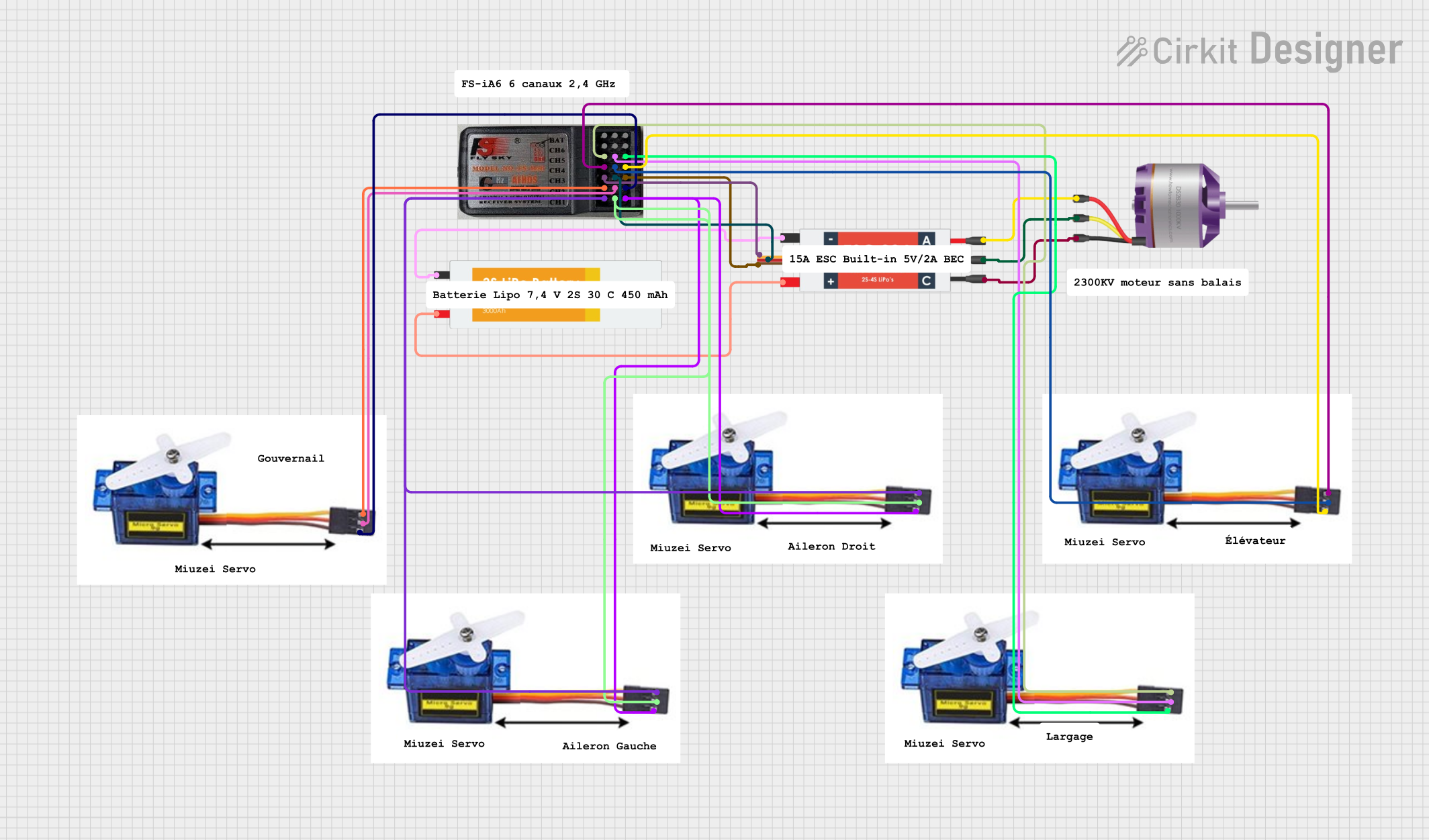
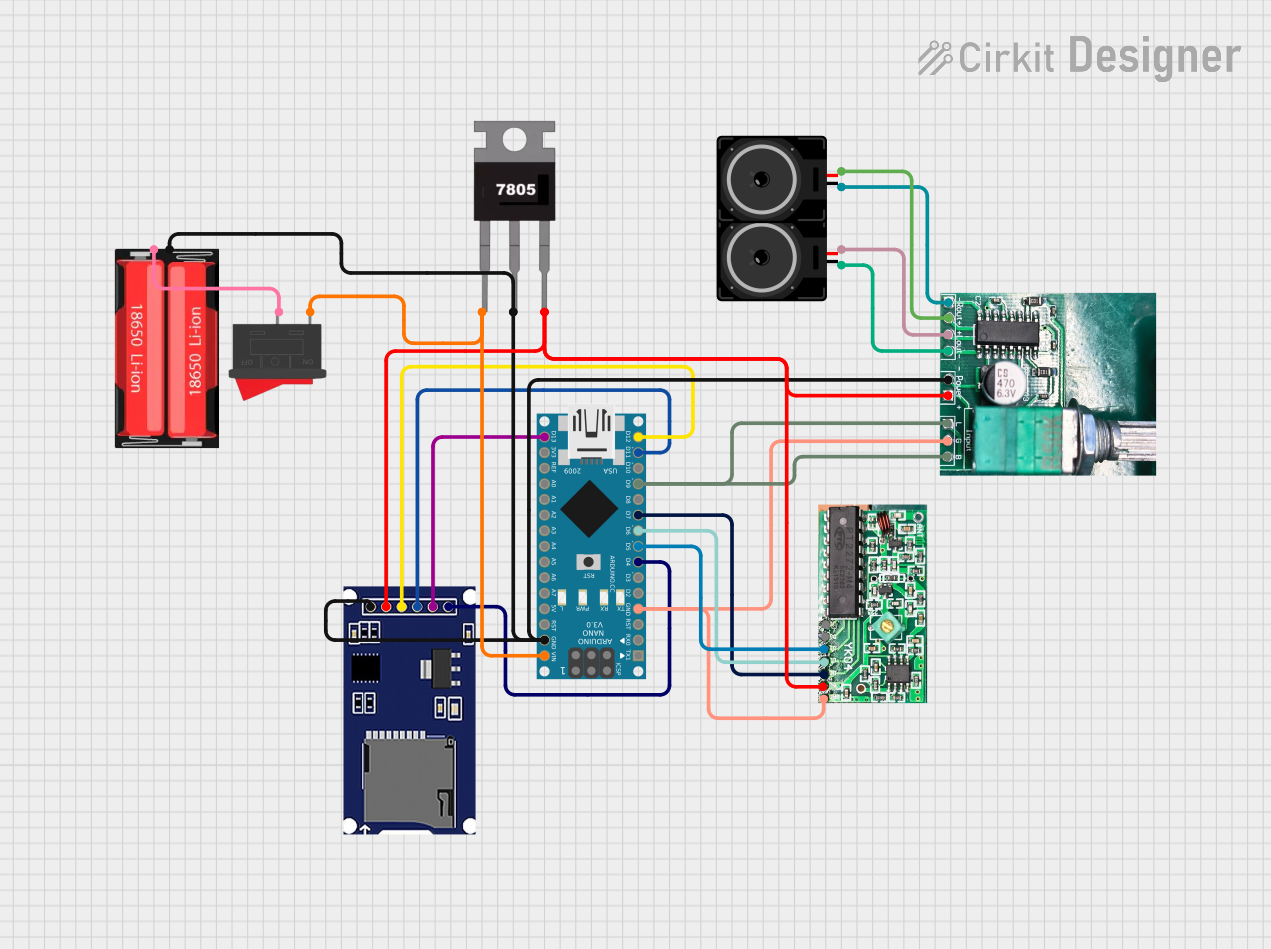
Explore Projects Built with RC Reciever 6 channels
Common Applications and Use Cases
- RC airplanes and helicopters
- RC cars and boats
- DIY robotics
- Educational projects
Technical Specifications
Key Technical Details
- Channels: 6
- Frequency Range: 2.4 - 2.48 GHz
- Modulation Type: GFSK
- Sensitivity: 1024
- Power Input: 4.0-6.5V DC
- Antenna Length: 26mm * 2 (dual antenna)
- Dimensions: 45 x 23 x 9mm
- Weight: 13g
Pin Configuration and Descriptions
| Pin Number | Function | Description |
|---|---|---|
| 1 | Channel 1 | Typically used for throttle control |
| 2 | Channel 2 | Typically used for aileron control |
| 3 | Channel 3 | Typically used for elevator control |
| 4 | Channel 4 | Typically used for rudder control |
| 5 | Channel 5 | Auxiliary channel (e.g., landing gear) |
| 6 | Channel 6 | Auxiliary channel (e.g., flaps) |
| B/VCC | Power Supply | Positive terminal for power supply (4.0-6.5V) |
| G/GRD | Ground | Ground terminal |
Usage Instructions
How to Use the Component in a Circuit
- Power Connection: Connect the power supply to the B/VCC and G/GRD pins, ensuring that the voltage is within the specified range (4.0-6.5V DC).
- Channel Connection: Connect the signal wires from your servos or other control devices to the appropriate channel pins (1-6) on the receiver.
- Binding: Before use, the receiver must be bound to a compatible FlySky transmitter. Follow the binding instructions provided by the manufacturer.
- Testing: Test each channel by operating the corresponding control on the transmitter to ensure proper response from the connected devices.
Important Considerations and Best Practices
- Ensure that the antenna is properly installed and positioned for optimal signal reception.
- Avoid placing the receiver near metal objects or electronic interference sources.
- Check and double-check all connections before powering up the system.
- Use a regulated power supply to prevent voltage spikes that could damage the receiver.
Troubleshooting and FAQs
Common Issues Users Might Face
- Signal Loss: Ensure that the antennas are not blocked or damaged, and check for sources of interference.
- Unresponsive Channels: Verify that the servos or control devices are properly connected and functioning.
- Binding Issues: Make sure that the receiver is in binding mode and that the transmitter is compatible and in close proximity during the binding process.
Solutions and Tips for Troubleshooting
- Rebinding: If the receiver is not responding to the transmitter, try rebinding the devices.
- Power Cycling: Turn off the power to the receiver and transmitter, wait a few moments, and then turn them back on to reset the system.
- Check Connections: Loose or incorrect connections can cause various issues. Ensure all connections are secure and correct.
FAQs
Q: Can I use the FS-R6B with any FlySky transmitter? A: The FS-R6B is compatible with FlySky transmitters that support the 2.4GHz AFHDS (Automatic Frequency Hopping Digital System) protocol.
Q: How do I know if my receiver is receiving a signal? A: Most receivers, including the FS-R6B, have an LED indicator that lights up when a signal is being received.
Q: What should I do if one of the channels is not working? A: Check the servo or control device connected to that channel, inspect the wiring, and ensure that the transmitter is programmed correctly for that channel.
Example Code for Arduino UNO
Below is an example of how to read the PWM signals from the FS-R6B receiver using an Arduino UNO. This code assumes that the receiver's channels are connected to the Arduino's digital pins 2 through 7.
#include <Servo.h>

// Create Servo objects for each channel
Servo channel1;
Servo channel2;
Servo channel3;
Servo channel4;
Servo channel5;
Servo channel6;

void setup() {
  // Attach each channel to the corresponding pin
  channel1.attach(2);
  channel2.attach(3);
  channel3.attach(4);
  channel4.attach(5);
  channel5.attach(6);
  channel6.attach(7);
}

void loop() {
  // Read the pulse width from each channel
  int pulseWidth1 = pulseIn(2, HIGH);
  int pulseWidth2 = pulseIn(3, HIGH);
  int pulseWidth3 = pulseIn(4, HIGH);
  int pulseWidth4 = pulseIn(5, HIGH);
  int pulseWidth5 = pulseIn(6, HIGH);
  int pulseWidth6 = pulseIn(7, HIGH);

  // Use the pulse width values as needed
  // For example, you can control servos or other actuators
}
Note: The pulseIn() function measures the length of the pulse (in microseconds) on a pin. For standard RC receivers, this pulse width typically ranges from 1000 to 2000 microseconds, corresponding to the control positions on the transmitter.
Remember to keep your code comments concise and within the 80 character line length limit.