Cirkit Designer Logo
Cirkit Designer
Your all-in-one circuit design IDE
Home / 
Component Documentation

How to Use Adafruit PCF8591: Examples, Pinouts, and Specs

Image of Adafruit PCF8591
Cirkit Designer LogoDesign with Adafruit PCF8591 in Cirkit Designer

Introduction

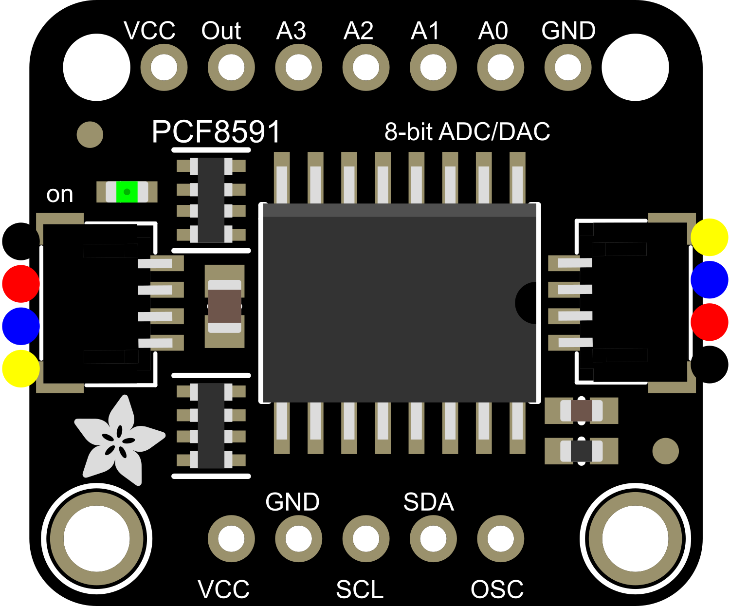
The Adafruit PCF8591 is a versatile breakout board featuring the PCF8591 IC, which is a single-chip, single-supply low-power 8-bit CMOS data acquisition device with four analog inputs, one analog output, and a serial I²C-bus interface. This component is commonly used in applications requiring analog-to-digital conversion (ADC) and digital-to-analog conversion (DAC), such as sensor data reading, light intensity measurement, and simple feedback control systems.

Explore Projects Built with Adafruit PCF8591

Use Cirkit Designer to design, explore, and prototype these projects online. Some projects support real-time simulation. Click "Open Project" to start designing instantly!
Raspberry Pi 4B-Based Current Monitoring System with I2C OLED Display
Image of Virtual Energy Monitoring Circuit: A project utilizing Adafruit PCF8591 in a practical application
This circuit features a Raspberry Pi 4B as the central processing unit, interfaced with an Adafruit ADS1115 16-bit I2C ADC for analog-to-digital conversion and a 0.96" OLED display for visual output. The ADS1115 is connected to a current sensor for measuring electrical current, with the sensor's output and burden pins connected to the ADC's analog input channels. The Raspberry Pi communicates with both the ADC and the OLED display over the I2C bus, using its GPIO2 and GPIO3 pins for data (SDA) and clock (SCL) lines, respectively.
Cirkit Designer LogoOpen Project in Cirkit Designer
Raspberry Pi 4B with I2C Current Sensing and OLED Display
Image of iot task 2: A project utilizing Adafruit PCF8591 in a practical application
This circuit features a Raspberry Pi 4B as the central processing unit, interfaced with an Adafruit ADS1115 16-bit I2C ADC for analog-to-digital conversion and a 0.96" OLED display for visual output. The ADC is connected to a current sensor for measuring electrical current, with the sensor's output connected to the ADC's AIN0 pin and the burden resistor connected to AIN1. The Raspberry Pi communicates with both the ADC and the OLED display over the I2C bus, using GPIO2 (SDA) and GPIO3 (SCL) for data exchange.
Cirkit Designer LogoOpen Project in Cirkit Designer
Battery-Powered Smart Sensor Hub with Adafruit QT Py RP2040
Image of wearable final: A project utilizing Adafruit PCF8591 in a practical application
This circuit features an Adafruit QT Py RP2040 microcontroller interfaced with an APDS9960 proximity sensor, an MPU6050 accelerometer and gyroscope, and an OLED display via I2C communication. It also includes a buzzer controlled by the microcontroller and is powered by a 3.7V LiPo battery with a toggle switch for power control.
Cirkit Designer LogoOpen Project in Cirkit Designer
Battery-Powered Smart Light with Proximity Sensor and OLED Display using Adafruit QT Py RP2040
Image of lab: A project utilizing Adafruit PCF8591 in a practical application
This circuit is a portable, battery-powered system featuring an Adafruit QT Py RP2040 microcontroller that interfaces with an OLED display, a proximity sensor, an accelerometer, and an RGB LED strip. The system is powered by a lithium-ion battery with a step-up boost converter to provide 5V for the LED strip, and it includes a toggle switch for power control. The microcontroller communicates with the sensors and display via I2C.
Cirkit Designer LogoOpen Project in Cirkit Designer

Explore Projects Built with Adafruit PCF8591

Use Cirkit Designer to design, explore, and prototype these projects online. Some projects support real-time simulation. Click "Open Project" to start designing instantly!
Image of Virtual Energy Monitoring Circuit: A project utilizing Adafruit PCF8591 in a practical application
Raspberry Pi 4B-Based Current Monitoring System with I2C OLED Display
This circuit features a Raspberry Pi 4B as the central processing unit, interfaced with an Adafruit ADS1115 16-bit I2C ADC for analog-to-digital conversion and a 0.96" OLED display for visual output. The ADS1115 is connected to a current sensor for measuring electrical current, with the sensor's output and burden pins connected to the ADC's analog input channels. The Raspberry Pi communicates with both the ADC and the OLED display over the I2C bus, using its GPIO2 and GPIO3 pins for data (SDA) and clock (SCL) lines, respectively.
Cirkit Designer LogoOpen Project in Cirkit Designer
Image of iot task 2: A project utilizing Adafruit PCF8591 in a practical application
Raspberry Pi 4B with I2C Current Sensing and OLED Display
This circuit features a Raspberry Pi 4B as the central processing unit, interfaced with an Adafruit ADS1115 16-bit I2C ADC for analog-to-digital conversion and a 0.96" OLED display for visual output. The ADC is connected to a current sensor for measuring electrical current, with the sensor's output connected to the ADC's AIN0 pin and the burden resistor connected to AIN1. The Raspberry Pi communicates with both the ADC and the OLED display over the I2C bus, using GPIO2 (SDA) and GPIO3 (SCL) for data exchange.
Cirkit Designer LogoOpen Project in Cirkit Designer
Image of wearable final: A project utilizing Adafruit PCF8591 in a practical application
Battery-Powered Smart Sensor Hub with Adafruit QT Py RP2040
This circuit features an Adafruit QT Py RP2040 microcontroller interfaced with an APDS9960 proximity sensor, an MPU6050 accelerometer and gyroscope, and an OLED display via I2C communication. It also includes a buzzer controlled by the microcontroller and is powered by a 3.7V LiPo battery with a toggle switch for power control.
Cirkit Designer LogoOpen Project in Cirkit Designer
Image of lab: A project utilizing Adafruit PCF8591 in a practical application
Battery-Powered Smart Light with Proximity Sensor and OLED Display using Adafruit QT Py RP2040
This circuit is a portable, battery-powered system featuring an Adafruit QT Py RP2040 microcontroller that interfaces with an OLED display, a proximity sensor, an accelerometer, and an RGB LED strip. The system is powered by a lithium-ion battery with a step-up boost converter to provide 5V for the LED strip, and it includes a toggle switch for power control. The microcontroller communicates with the sensors and display via I2C.
Cirkit Designer LogoOpen Project in Cirkit Designer

Technical Specifications

Key Technical Details

  • Supply Voltage (VCC): 2.5V to 6V
  • Input/Output Voltage (VI/O): 0V to VCC
  • Analog Inputs: 4-channel, single-ended or 3-channel differential
  • Analog Output: 1-channel, 8-bit resolution
  • Resolution: 8-bit for both ADC and DAC
  • I²C Address: Selectable via jumpers (0x48 to 0x4F)
  • Operating Temperature: -40°C to +85°C

Pin Configuration and Descriptions

Pin Number Pin Name Description
1 AIN0 Analog input channel 0
2 AIN1 Analog input channel 1
3 AIN2 Analog input channel 2
4 AIN3 Analog input channel 3
5 AOUT Analog output
6 AGND Analog ground
7 VREF Reference voltage for ADC and DAC
8 VSS Power supply ground
9 SCL Serial clock line for I²C
10 SDA Serial data line for I²C
11 VDD Positive power supply
12 OS Output enable for the DAC, active low

Usage Instructions

Integration with a Circuit

  1. Power Supply: Connect VDD to a 2.5V to 6V power source and VSS to ground.
  2. I²C Communication: Connect SDA and SCL to your microcontroller's I²C data and clock lines.
  3. Analog Inputs: Connect your analog signals to AIN0 through AIN3 as needed.
  4. Analog Output: AOUT provides the DAC output, which can be used to control analog devices.
  5. Reference Voltage: VREF should be connected to the desired reference voltage for ADC/DAC operations.

Important Considerations and Best Practices

  • Ensure that the input voltage does not exceed the VCC voltage to prevent damage.
  • Use pull-up resistors on the SDA and SCL lines if your microcontroller does not have built-in pull-ups.
  • To minimize noise, keep analog signal paths as short as possible and away from high-current traces.
  • Configure the I²C address using the onboard jumpers if multiple I²C devices are used on the same bus.

Example Code for Arduino UNO

#include <Wire.h>

// PCF8591 default I2C address
const int PCF8591 = 0x48;

void setup() {
  Wire.begin(); // Join I2C bus
  Serial.begin(9600); // Start serial communication at 9600 baud
}

void loop() {
  Wire.beginTransmission(PCF8591); // Start transmission to device 
  Wire.write(0x04); // Control byte - enable DAC, enable ADC0
  Wire.endTransmission(); // End transmission
  
  Wire.requestFrom(PCF8591, 2); // Request 2 bytes from the PCF8591
  Wire.read(); // Read first byte (dummy read)
  int analogValue = Wire.read(); // Read second byte (ADC0 value)
  
  Serial.println(analogValue); // Print the value to the serial monitor
  
  delay(1000); // Wait for 1 second
}

This example initializes the I²C communication and reads the analog value from channel AIN0 every second, then prints it to the serial monitor.

Troubleshooting and FAQs

Common Issues

  • No response from the device: Check the wiring, especially the I²C connections, and ensure that the correct I²C address is used.
  • Inaccurate readings: Verify that VREF is correctly set and that there is no noise in the analog signal path.
  • Unable to write to DAC: Ensure that the OS pin is pulled low to enable the output.

Solutions and Tips for Troubleshooting

  • Use a multimeter to check for proper voltage levels at VDD and VREF.
  • If using long wires for I²C, consider using a lower pull-up resistor value to maintain signal integrity.
  • Check for solder bridges or cold solder joints that might be causing shorts or open circuits.

FAQs

Q: Can I use this board with a 5V Arduino? A: Yes, the PCF8591 can operate at 5V and is compatible with 5V Arduino boards.

Q: How do I change the I²C address? A: The I²C address can be changed by adjusting the jumpers on the board to one of the eight possible addresses (0x48 to 0x4F).

Q: Can I use differential inputs with this board? A: Yes, the PCF8591 allows for three differential input measurements. Refer to the datasheet for configuring differential inputs.

Q: What is the maximum sampling rate of the ADC? A: The maximum sampling rate depends on the I²C clock frequency but typically is around 100 samples per second.

Remember to always consult the PCF8591 datasheet for detailed information and specifications.