How to Use LED: Two Pin (blue): Examples, Pinouts, and Specs
Introduction
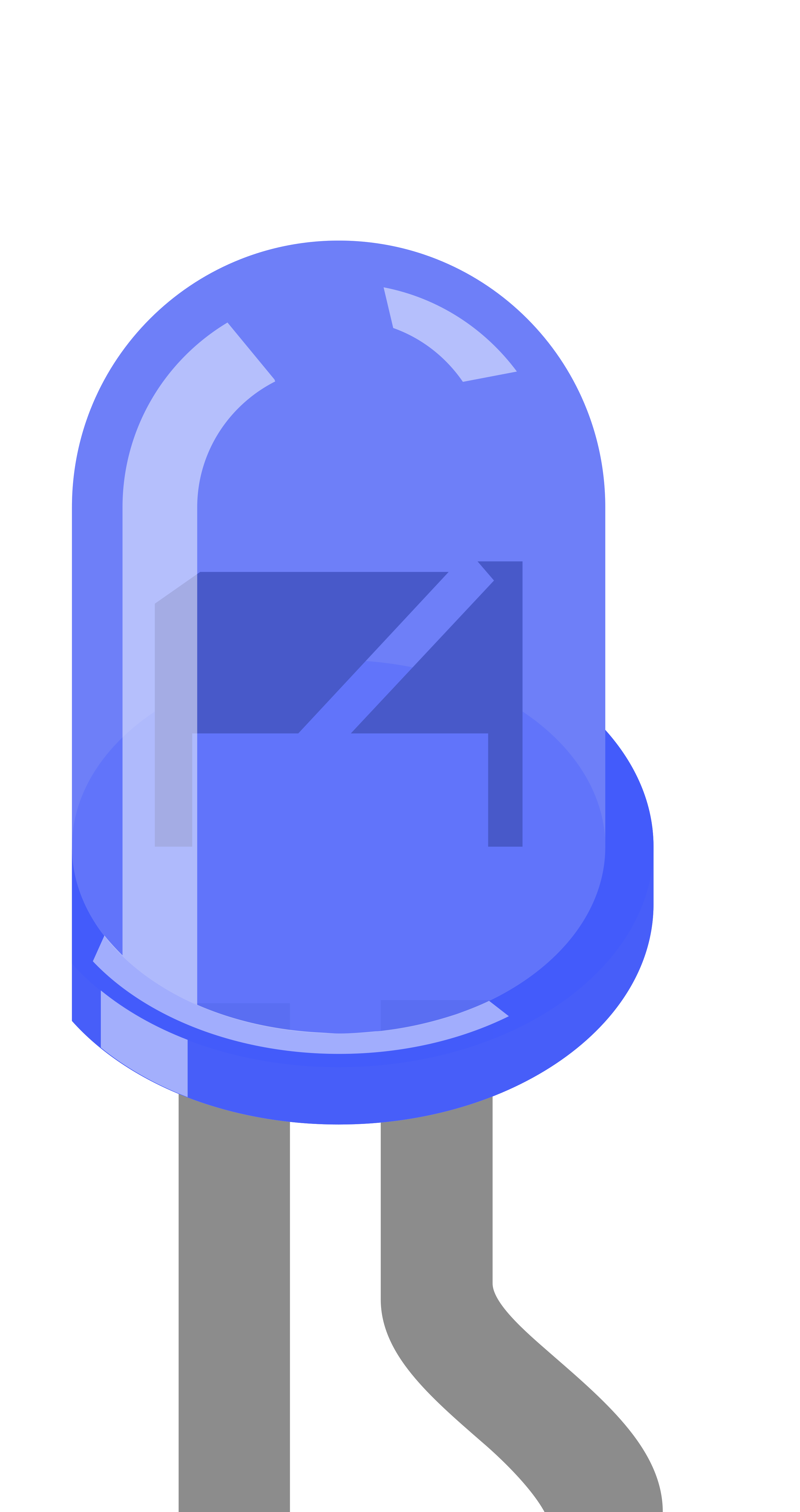
A blue LED (Light-Emitting Diode) with two pins is a semiconductor light source that emits blue light when an electric current passes through it. This type of LED is widely used in various applications such as indicator lights, backlighting, display panels, and DIY electronics projects due to its bright and vibrant color.
Explore Projects Built with LED: Two Pin (blue)

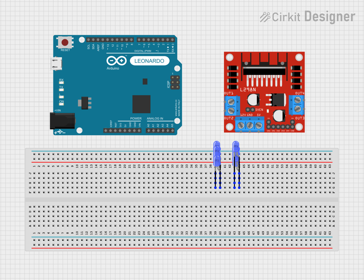
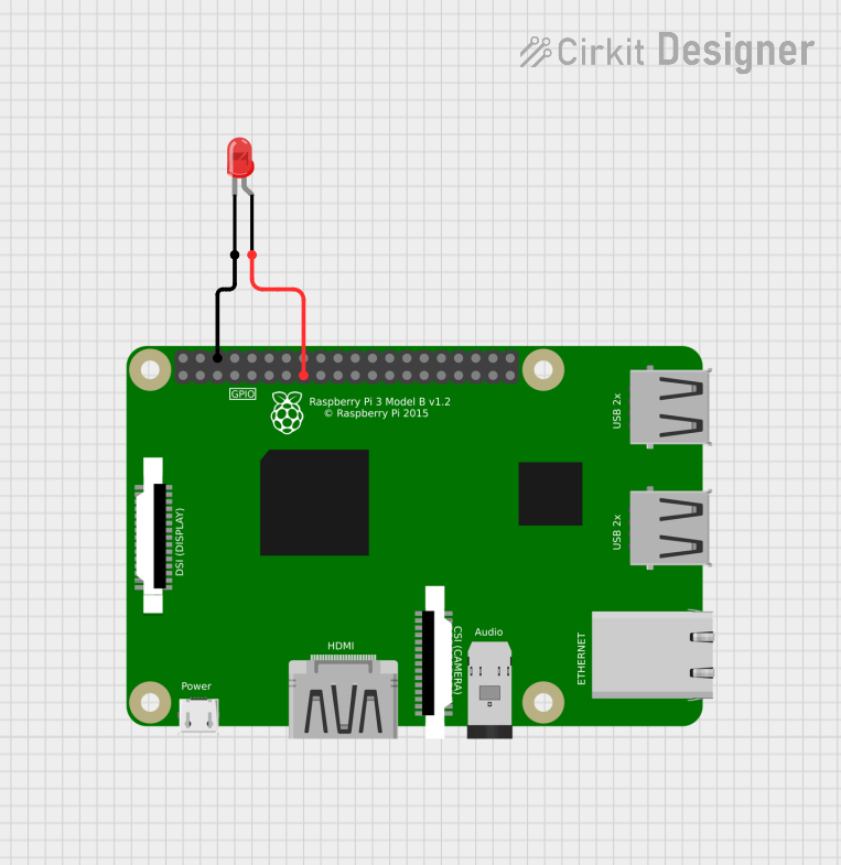

Explore Projects Built with LED: Two Pin (blue)
Common Applications and Use Cases
- Indicator lights for power status
- Backlighting for LCD displays
- Decorative and accent lighting
- DIY electronics and hobbyist projects
- Signal and symbol illumination in devices
Technical Specifications
Key Technical Details
- Forward Voltage (Vf): Typically 3.0V to 3.4V
- Forward Current (If): Recommended 20mA (max. 30mA)
- Luminous Intensity: Varies with manufacturer, typically around 150-600 mcd
- Wavelength: Approximately 465-475 nm (nanometers)
- Viewing Angle: Typically 120 degrees
Pin Configuration and Descriptions
| Pin Number | Name | Description |
|---|---|---|
| 1 | Anode (+) | Longer pin, to be connected to the positive supply voltage |
| 2 | Cathode (-) | Shorter pin, to be connected to the ground (GND) |
Usage Instructions
How to Use the Component in a Circuit
- Identify the Pins: Determine which pin is the anode (longer pin) and which is the cathode (shorter pin).
- Current Limiting Resistor: Connect a current limiting resistor in series with the LED to prevent it from drawing excessive current. The value of the resistor can be calculated using Ohm's law:
R = (Vsupply - Vf) / If. - Power Supply: Connect the anode to the positive terminal of your power supply and the cathode to the negative terminal through the resistor.
Important Considerations and Best Practices
- Resistor Calculation: Ensure the resistor value is calculated based on the supply voltage to prevent damage to the LED.
- Polarity: Do not reverse the polarity of the LED, as it is a diode and will not light up if connected incorrectly.
- Heat Dissipation: Although LEDs do not generate much heat, ensure there is adequate space around the LED for heat dissipation.
Example Circuit with Arduino UNO
// Define the pin where the LED is connected
const int ledPin = 13; // LED connected to digital pin 13

void setup() {
  pinMode(ledPin, OUTPUT); // Set the LED pin as an output
}

void loop() {
  digitalWrite(ledPin, HIGH); // Turn the LED on
  delay(1000);                // Wait for a second
  digitalWrite(ledPin, LOW);  // Turn the LED off
  delay(1000);                // Wait for a second
}
Note: When connecting the LED to an Arduino, ensure you use a current limiting resistor (typically 220 ohms for a 5V supply) between the digital pin and the anode of the LED.
Troubleshooting and FAQs
Common Issues
- LED Not Lighting Up: Check if the LED is connected in the correct orientation and if the current limiting resistor is in place.
- LED Burnt Out: This can happen if the current exceeds the maximum rating. Always use a current limiting resistor.
Solutions and Tips for Troubleshooting
- Check Connections: Ensure all connections are secure and the polarity is correct.
- Resistor Value: Verify that the resistor value is appropriate for the supply voltage.
- Power Supply: Confirm that the power supply is functioning and providing the correct voltage.
FAQs
Q: Can I connect the LED directly to a 5V supply? A: No, you should always use a current limiting resistor to protect the LED from drawing too much current.
Q: How do I know if my LED is damaged? A: If the LED does not light up when the correct voltage is applied, and all connections are correct, it may be damaged.
Q: Can I use a 9V battery to power the LED? A: Yes, but you will need to calculate the value of the current limiting resistor accordingly to handle the higher voltage.