How to Use x9c104: Examples, Pinouts, and Specs
Introduction
The X9C104 is a digital potentiometer manufactured in China, designed to provide variable resistance control through a digital interface. With a resistance range of 100kΩ, it is a versatile component suitable for a variety of applications. The X9C104 allows precise adjustment of resistance values, making it ideal for use in volume control, signal conditioning, sensor calibration, and other applications requiring fine-tuned resistance settings.
Explore Projects Built with x9c104

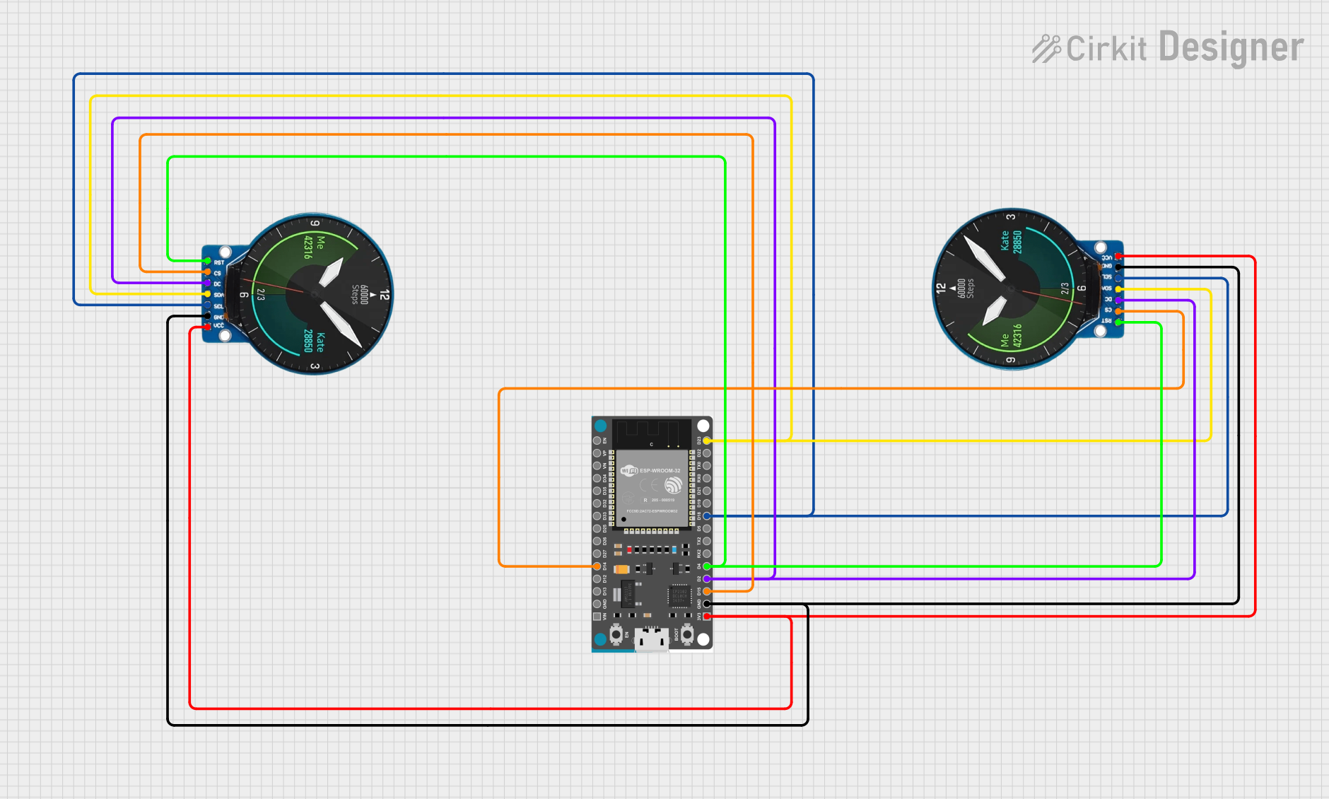
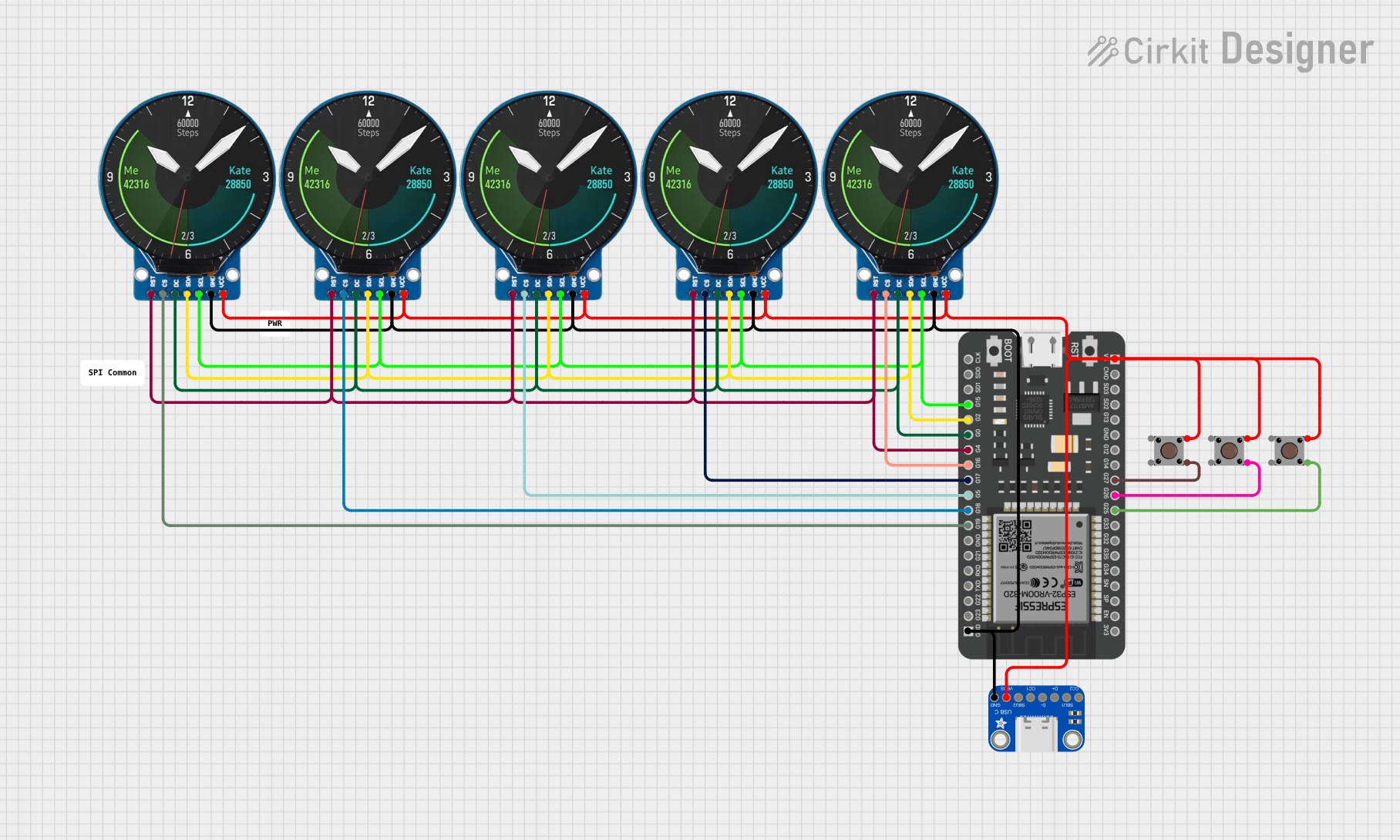

Explore Projects Built with x9c104
Common Applications
- Audio volume control
- Signal conditioning in analog circuits
- Sensor calibration and tuning
- Adjustable gain in amplifiers
- Programmable resistor networks
Technical Specifications
The X9C104 is a 100kΩ digital potentiometer with 100 wiper positions, allowing for fine-grained resistance adjustments. It operates via a simple digital interface, making it easy to integrate into microcontroller-based systems.
Key Specifications
| Parameter | Value |
|---|---|
| Resistance Range | 100kΩ |
| Number of Wiper Steps | 100 |
| Wiper Resistance | 40Ω (typical) |
| Supply Voltage (Vcc) | 2.7V to 5.5V |
| Operating Current | 3mA (typical) |
| Standby Current | 1µA (typical) |
| Interface | Up/Down control with CS pin |
| Operating Temperature | -40°C to +85°C |
| Package Type | 8-pin DIP/SOIC |
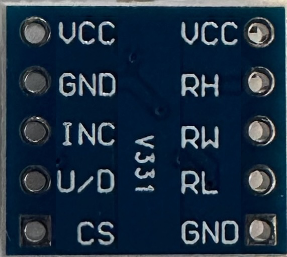
Pin Configuration and Descriptions
The X9C104 is an 8-pin device. The table below describes each pin:
| Pin Number | Pin Name | Description |
|---|---|---|
| 1 | CS | Chip Select: Activates the device when pulled low. |
| 2 | INC | Increment: Adjusts the wiper position when toggled. |
| 3 | U/D | Up/Down: Determines the direction of wiper movement (high = up, low = down). |
| 4 | Vss | Ground: Connect to system ground. |
| 5 | Vw | Wiper Terminal: Connect to the adjustable output. |
| 6 | Vl | Low Terminal: Connect to the lower end of the resistor. |
| 7 | Vh | High Terminal: Connect to the upper end of the resistor. |
| 8 | Vcc | Power Supply: Connect to a 2.7V to 5.5V power source. |
Usage Instructions
The X9C104 is straightforward to use in a circuit. It requires a digital control signal to adjust the resistance between its terminals. Below are the steps and considerations for using the X9C104:
Basic Circuit Connection
- Power Supply: Connect the Vcc pin to a 2.7V to 5.5V power source and the Vss pin to ground.
- Resistor Terminals: Connect Vh to the high end of the resistor network, Vl to the low end, and Vw to the adjustable wiper output.
- Control Pins:
- Connect the CS pin to a digital output pin of a microcontroller.
- Connect the INC pin to another digital output pin for toggling the wiper position.
- Connect the U/D pin to a digital output pin to set the direction of wiper movement.
Important Considerations
- The CS pin must be pulled low to enable the device. When CS is high, the device is inactive.
- The INC pin must be toggled (high to low) to adjust the wiper position. The U/D pin determines whether the wiper moves up or down.
- The wiper position is non-volatile, meaning it retains its position even after power is removed.
Example: Using X9C104 with Arduino UNO
Below is an example of how to control the X9C104 using an Arduino UNO:
// Define pin connections for the X9C104
const int CS_PIN = 10;  // Chip Select pin
const int INC_PIN = 9;  // Increment pin
const int UD_PIN = 8;   // Up/Down pin

void setup() {
  // Set pin modes
  pinMode(CS_PIN, OUTPUT);
  pinMode(INC_PIN, OUTPUT);
  pinMode(UD_PIN, OUTPUT);

  // Initialize pins
  digitalWrite(CS_PIN, HIGH);  // Disable the device initially
  digitalWrite(INC_PIN, HIGH); // Set INC to high
  digitalWrite(UD_PIN, LOW);   // Set direction to down
}

void loop() {
  // Example: Increase resistance by 10 steps
  digitalWrite(CS_PIN, LOW);  // Enable the device
  digitalWrite(UD_PIN, HIGH); // Set direction to up

  for (int i = 0; i < 10; i++) {
    digitalWrite(INC_PIN, LOW);  // Toggle INC pin
    delay(1);                    // Short delay
    digitalWrite(INC_PIN, HIGH); // Complete the toggle
    delay(1);                    // Short delay
  }

  digitalWrite(CS_PIN, HIGH); // Disable the device
  delay(1000);                // Wait for 1 second

  // Example: Decrease resistance by 5 steps
  digitalWrite(CS_PIN, LOW);  // Enable the device
  digitalWrite(UD_PIN, LOW);  // Set direction to down

  for (int i = 0; i < 5; i++) {
    digitalWrite(INC_PIN, LOW);  // Toggle INC pin
    delay(1);                    // Short delay
    digitalWrite(INC_PIN, HIGH); // Complete the toggle
    delay(1);                    // Short delay
  }

  digitalWrite(CS_PIN, HIGH); // Disable the device
  delay(1000);                // Wait for 1 second
}
Best Practices
- Use decoupling capacitors (e.g., 0.1µF) near the Vcc pin to stabilize the power supply.
- Avoid toggling the INC pin too quickly; ensure a minimum pulse width of 1µs.
- Ensure the CS pin is high when not adjusting the wiper to prevent unintended changes.
Troubleshooting and FAQs
Common Issues
Wiper Position Not Changing:
- Ensure the CS pin is pulled low during adjustments.
- Verify that the INC pin is toggled correctly with sufficient delay.
Incorrect Resistance Output:
- Check the connections to Vh, Vl, and Vw.
- Ensure the U/D pin is set to the correct direction.
Device Not Responding:
- Verify the power supply voltage is within the specified range (2.7V to 5.5V).
- Check for loose or incorrect connections.
FAQs
Q: Can the X9C104 retain its wiper position after power is removed?
A: Yes, the X9C104 has non-volatile memory and retains its wiper position even after power is disconnected.
Q: What is the maximum current the wiper can handle?
A: The wiper can handle a maximum current of 1mA. Exceeding this limit may damage the device.
Q: Can I use the X9C104 with a 3.3V microcontroller?
A: Yes, the X9C104 operates within a supply voltage range of 2.7V to 5.5V, making it compatible with 3.3V systems.
Q: How precise is the resistance adjustment?
A: The X9C104 provides 100 discrete wiper positions, allowing for fine-grained resistance adjustments.