How to Use SparkFun_LIS3DH-Breakout: Examples, Pinouts, and Specs
Introduction
The SparkFun LIS3DH Breakout is a versatile and powerful accelerometer breakout board that features the LIS3DH sensor. This sensor is a three-axis accelerometer that provides high-resolution measurement at up to ±16g. It is designed for low-power consumption and operates on a supply voltage from 1.71V to 3.6V, making it ideal for battery-powered applications. The LIS3DH is commonly used in mobile devices, gaming controllers, motion detection systems, and various other applications where motion or inclination sensing is required.
Explore Projects Built with SparkFun_LIS3DH-Breakout
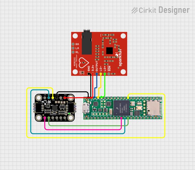
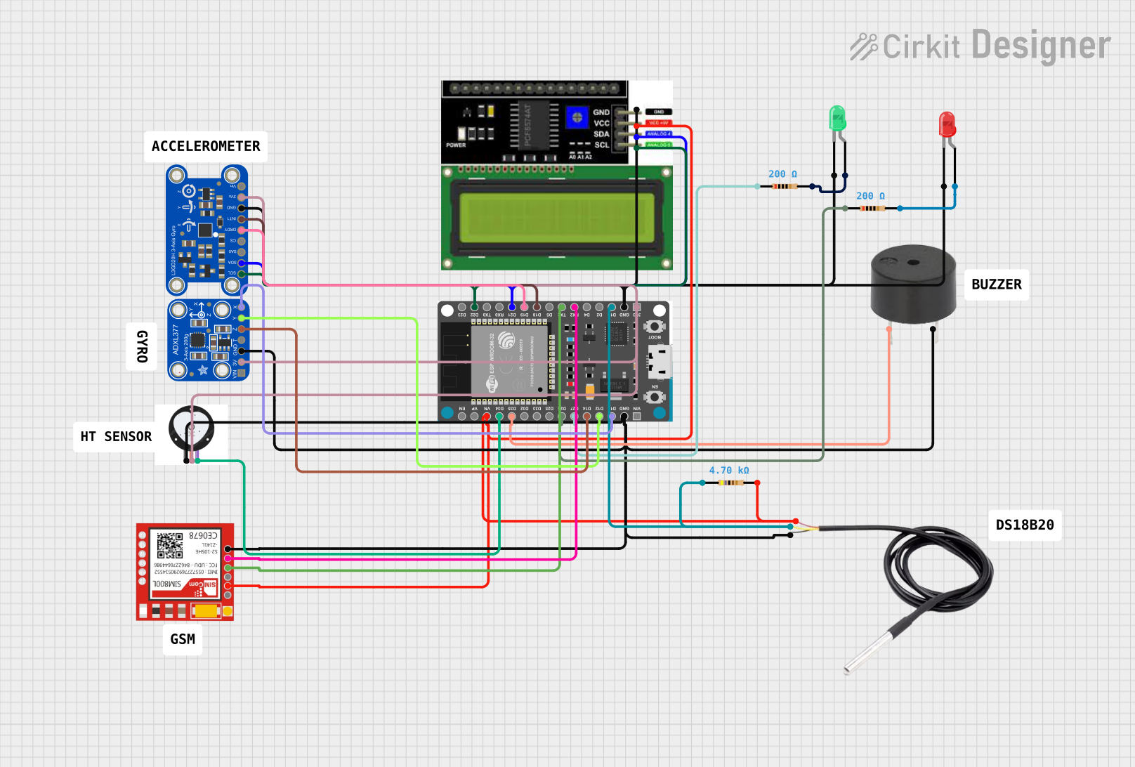
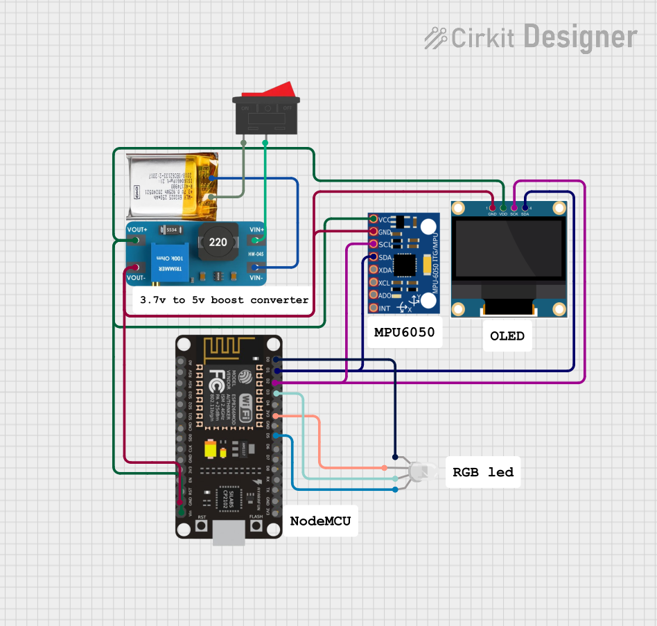
Explore Projects Built with SparkFun_LIS3DH-Breakout
Technical Specifications
Key Technical Details
- Supply Voltage (VDD): 1.71V to 3.6V
- Output Data Rates (ODR): 1 Hz to 5.3 kHz
- Acceleration Ranges: ±2g, ±4g, ±8g, ±16g
- Interface: I2C and SPI (4-wire and 3-wire)
- Resolution: 16-bit
- Operating Temperature Range: -40°C to +85°C
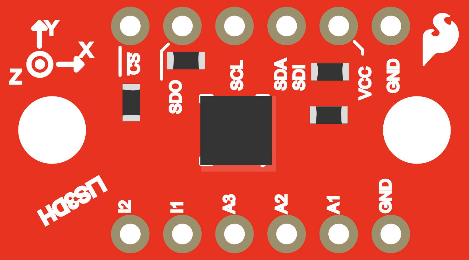
Pin Configuration and Descriptions
| Pin Number | Pin Name | Description |
|---|---|---|
| 1 | GND | Ground connection for power and logic |
| 2 | VCC | Supply voltage (1.71V to 3.6V) |
| 3 | SCL/SPC | I2C Serial Clock / SPI Serial Clock |
| 4 | SDA/SDI | I2C Serial Data / SPI Serial Data In |
| 5 | SDO | SPI Serial Data Out / I2C Address Selection |
| 6 | CS | SPI Chip Select (active low) |
| 7 | INT1 | Interrupt 1 output (configurable) |
| 8 | INT2 | Interrupt 2 output (configurable) |
Usage Instructions
How to Use the Component in a Circuit
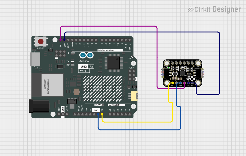
Powering the Device: Connect the VCC pin to a power supply within the range of 1.71V to 3.6V. Connect the GND pin to the ground of your power supply.
Selecting the Interface: Choose between I2C or SPI for communication. For I2C, use the SCL and SDA pins. For SPI, use the SPC, SDI, SDO, and CS pins.
Setting Up Interrupts (Optional): The INT1 and INT2 pins can be configured to output interrupts based on certain conditions detected by the accelerometer. Connect these to microcontroller interrupt pins if required.
Mounting: Ensure the breakout board is securely mounted to prevent noise and inaccuracies in the readings.
Important Considerations and Best Practices
- Decoupling Capacitor: Place a 0.1 µF capacitor close to the VCC and GND pins to filter out power supply noise.
- I2C Pull-up Resistors: If using I2C, ensure that there are pull-up resistors on the SCL and SDA lines.
- SPI Settings: When using SPI, configure the microcontroller for Mode 3 (CPOL = 1, CPHA = 1).
- Data Rate Configuration: Configure the Output Data Rate (ODR) according to the application's requirements for power consumption and performance.
- Axis Alignment: Ensure that the breakout board is aligned correctly according to the axes you wish to measure.
Example Code for Arduino UNO
#include <Wire.h>
#include <SparkFunLIS3DH.h>
#include <SPI.h>

LIS3DH myIMU; // Default constructor is I2C, addr 0x19.

void setup() {
  Serial.begin(9600);
  Wire.begin();

  if (myIMU.begin() != 0) {
    Serial.println("Problem starting the sensor at 0x19.");
  } else {
    Serial.println("Sensor at 0x19 started.");
  }
}

void loop() {
  myIMU.readAccel(); // Read the accelerometer values and store them.

  // Print out the values.
  Serial.print("X: ");
  Serial.print(myIMU.x);
  Serial.print(" Y: ");
  Serial.print(myIMU.y);
  Serial.print(" Z: ");
  Serial.println(myIMU.z);

  delay(100); // Delay for readability.
}
Troubleshooting and FAQs
Common Issues
- No Data or Incorrect Data: Ensure that the power supply is within the specified range and that the I2C/SPI connections are correct.
- Intermittent Connection: Check for loose connections or cold solder joints on the breakout board.
- Inaccurate Readings: Verify that the board is mounted securely and that there is no mechanical vibration affecting the sensor.
Solutions and Tips for Troubleshooting
- Check Power Supply: Use a multimeter to verify that the VCC and GND pins are receiving the correct voltage.
- I2C Address Conflict: Ensure that no other device on the I2C bus has a conflicting address.
- SPI Mode Mismatch: Double-check that the SPI mode is set correctly in your microcontroller's settings.
- Sensor Calibration: Perform a calibration routine if the application requires high accuracy.
FAQs
Q: Can the LIS3DH operate in both I2C and SPI simultaneously? A: No, the LIS3DH can operate in either I2C or SPI mode, but not both at the same time.
Q: How do I change the I2C address of the LIS3DH? A: The I2C address can be changed by connecting the SDO pin to either VCC or GND.
Q: What is the purpose of the INT1 and INT2 pins? A: These pins can be configured to output interrupts for events like data ready, free fall detection, or threshold exceedance.
Q: How do I set the acceleration range? A: The acceleration range can be set through the sensor's registers, which can be accessed via I2C or SPI commands.
Q: Can this sensor detect orientation? A: Yes, by comparing the acceleration on different axes, you can determine the orientation of the sensor relative to the ground.