How to Use HUB75: Examples, Pinouts, and Specs
Introduction
The HUB75 is a standardized interface widely used for connecting LED displays, particularly in large-scale video walls and digital signage. It provides a simple and efficient way to communicate between a display controller and LED modules. The HUB75 interface is known for its ability to handle high-speed data transmission, making it ideal for applications requiring vibrant, dynamic, and high-resolution visuals.
Explore Projects Built with HUB75


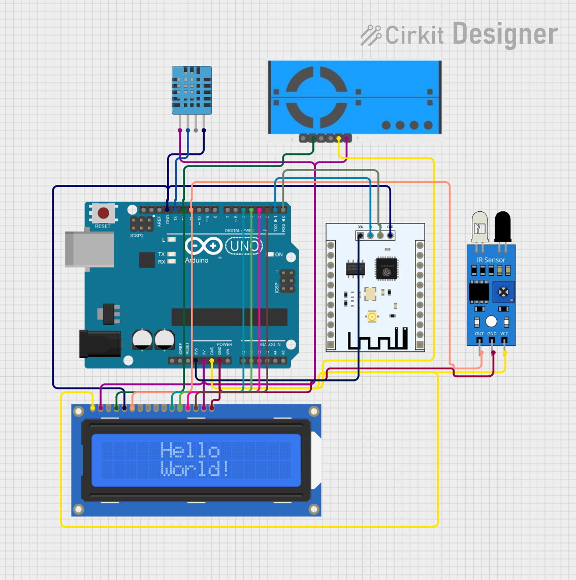
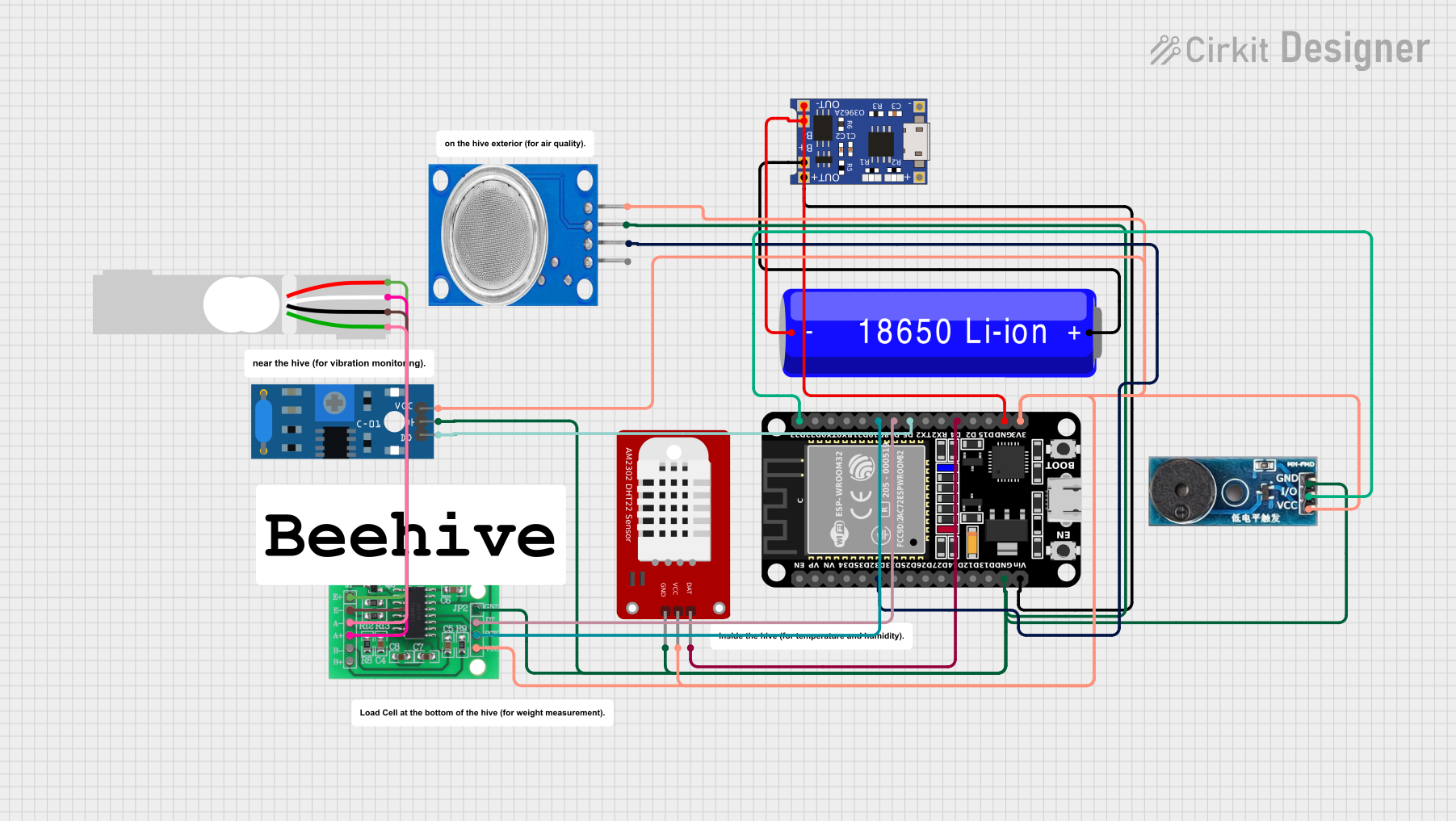
Explore Projects Built with HUB75
Common Applications and Use Cases
- Large-scale video walls in stadiums, malls, and public spaces
- Digital signage for advertising and information display
- LED matrix displays for animations, text, and graphics
- Interactive installations and art projects
- Scoreboards and event displays
Technical Specifications
Key Technical Details
- Voltage Supply: Typically 5V DC
- Data Protocol: Parallel data transmission
- Supported Colors: RGB (Red, Green, Blue)
- Refresh Rate: Up to 1920Hz (depending on the controller and LED module)
- Connector Type: 16-pin or 20-pin ribbon cable
- Maximum Resolution: Depends on the controller and LED module, commonly 32x16 or 64x32 pixels per panel
Pin Configuration and Descriptions
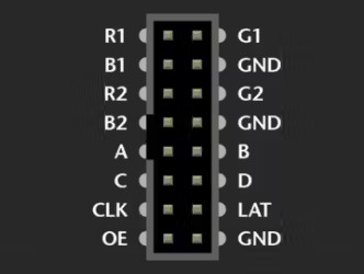
The HUB75 interface uses a 16-pin or 20-pin connector to transmit data and control signals. Below is the pinout for a standard 16-pin HUB75 connector:
| Pin | Name | Description |
|---|---|---|
| 1 | R1 | Red data for the first row |
| 2 | G1 | Green data for the first row |
| 3 | B1 | Blue data for the first row |
| 4 | R2 | Red data for the second row |
| 5 | G2 | Green data for the second row |
| 6 | B2 | Blue data for the second row |
| 7 | A | Row address bit 0 |
| 8 | B | Row address bit 1 |
| 9 | C | Row address bit 2 |
| 10 | D | Row address bit 3 |
| 11 | CLK | Clock signal for synchronizing data transfer |
| 12 | LAT | Latch signal to store data in the LED driver |
| 13 | OE | Output enable signal to control brightness |
| 14 | GND | Ground |
| 15 | VCC | Power supply (typically 5V) |
| 16 | E | Row address bit 4 (used in higher-resolution panels, optional in some models) |
For 20-pin connectors, additional pins may be used for extended functionality or higher resolutions.
Usage Instructions
How to Use the HUB75 in a Circuit
- Connect the HUB75 Interface: Use a ribbon cable to connect the HUB75 connector on the LED module to the corresponding connector on the controller board.
- Power the Module: Provide a stable 5V DC power supply to the VCC and GND pins of the HUB75 interface.
- Send Data: Use a compatible controller (e.g., Arduino, Raspberry Pi, or a dedicated LED controller) to send RGB data and control signals (CLK, LAT, OE, and row address bits).
- Configure the Controller: Ensure the controller is configured for the correct resolution and refresh rate of the LED module.
Important Considerations and Best Practices
- Power Supply: Ensure the power supply can handle the current requirements of the LED module, especially for large displays.
- Signal Integrity: Use short and high-quality ribbon cables to minimize signal degradation.
- Heat Management: Large LED displays can generate significant heat; ensure proper ventilation or cooling.
- Controller Compatibility: Verify that the controller supports the resolution and refresh rate of your LED module.
- Software Libraries: Use libraries like Adafruit GFX or PxMatrix for Arduino to simplify programming.
Example Code for Arduino UNO
Below is an example of how to control a HUB75-based LED matrix using an Arduino UNO and the PxMatrix library:
#include <PxMatrix.h>

// Define display size (e.g., 32x16 pixels)
#define DISPLAY_WIDTH 32
#define DISPLAY_HEIGHT 16

// Define pin connections
#define P_LAT 10  // Latch pin
#define P_A  A0   // Row address A
#define P_B  A1   // Row address B
#define P_C  A2   // Row address C
#define P_D  A3   // Row address D
#define P_OE 9    // Output enable pin
#define P_CLK 8   // Clock pin

// Create PxMatrix object
PxMatrix display(DISPLAY_WIDTH, DISPLAY_HEIGHT, P_LAT, P_OE, P_A, P_B, P_C, P_D, P_CLK);

void setup() {
  // Initialize the display
  display.begin(16); // Set brightness (0-255)
  display.setBrightness(100); // Adjust brightness level
}

void loop() {
  // Clear the display
  display.clearDisplay();

  // Draw a red rectangle
  display.fillRect(0, 0, 16, 8, display.color565(255, 0, 0));

  // Draw a green rectangle
  display.fillRect(16, 0, 16, 8, display.color565(0, 255, 0));

  // Draw a blue rectangle
  display.fillRect(0, 8, 16, 8, display.color565(0, 0, 255));

  // Update the display
  display.showBuffer();
  delay(500);
}
Notes:
- Install the PxMatrix library in the Arduino IDE before running the code.
- Adjust the pin definitions and display size to match your specific setup.
Troubleshooting and FAQs
Common Issues and Solutions
No Display Output:
- Verify all connections, especially the ribbon cable and power supply.
- Ensure the controller is properly configured for the LED module's resolution.
Flickering or Dim Display:
- Check the power supply for sufficient current output.
- Reduce the brightness level in the software to avoid overloading the power supply.
Incorrect Colors or Patterns:
- Ensure the data pins (R1, G1, B1, etc.) are correctly connected to the controller.
- Verify the software configuration matches the LED module's specifications.
Partial Display Not Working:
- Check for loose or damaged connections in the ribbon cable.
- Test the LED module with a different controller to rule out hardware issues.
FAQs
Can I daisy-chain multiple HUB75 panels? Yes, most HUB75 panels support daisy-chaining. Connect the output of one panel to the input of the next, and configure the controller for the combined resolution.
What is the maximum cable length for HUB75? For reliable operation, keep the ribbon cable length under 50cm. Use signal boosters for longer distances.
Can I use a 3.3V controller with HUB75? Most HUB75 modules require 5V logic levels. Use level shifters if your controller operates at 3.3V.
By following this documentation, you can effectively integrate and troubleshoot HUB75-based LED displays in your projects.