Cirkit Designer Logo
Cirkit Designer
Your all-in-one circuit design IDE
Home / 
Component Documentation

How to Use MCP3421: Examples, Pinouts, and Specs

Image of MCP3421
Cirkit Designer LogoDesign with MCP3421 in Cirkit Designer

Introduction

The MCP3421 is a high-resolution, low-power, 18-bit analog-to-digital converter (ADC) manufactured by Microchip. It features a single-channel input and an integrated programmable gain amplifier (PGA), allowing for precise measurements of small signals. The device communicates via the I2C protocol, making it easy to interface with microcontrollers and other digital systems. Its compact design and low power consumption make it ideal for battery-powered and portable applications.

Explore Projects Built with MCP3421

Use Cirkit Designer to design, explore, and prototype these projects online. Some projects support real-time simulation. Click "Open Project" to start designing instantly!
I2C-Controlled Relay Switching with ESP32 and MCP23017 for Home Automation
Image of Vloerverwarming: A project utilizing MCP3421 in a practical application
This circuit appears to be a control system utilizing two MCP23017 I/O expanders interfaced with an Olimex ESP32-EVB microcontroller via I2C communication, as indicated by the SDA and SCL connections with pull-up resistors. The MCP23017 expanders control an 8-channel relay module, allowing the microcontroller to switch various loads, potentially for home automation or industrial control. Additionally, there is an Adafruit ADS1115 16-bit ADC for analog signal measurement, and several heating actuators and a thermostat are connected, suggesting temperature control functionality.
Cirkit Designer LogoOpen Project in Cirkit Designer
ESP32-Based Vibration Motor Controller with I2C IO Expansion
Image of VIBRATYION: A project utilizing MCP3421 in a practical application
This circuit features an ESP32 Wroom Dev Kit microcontroller interfaced with an MCP23017 I/O expansion board via I2C communication, utilizing GPIO 21 and GPIO 22 for SDA and SCL lines, respectively. A vibration motor is controlled by an NPN transistor acting as a switch, with a diode for back EMF protection and a resistor to limit base current. The ESP32 can control the motor by sending signals to the MCP23017, which then interfaces with the transistor to turn the motor on or off.
Cirkit Designer LogoOpen Project in Cirkit Designer
MCP23017-Expanded I/O Interface with ADS1115 ADC and ESP32 Control
Image of door and window sensors: A project utilizing MCP3421 in a practical application
This circuit features two MCP23017 I/O expanders interfaced with multiple switches, allowing for the expansion of input capabilities. The MCP23017s are connected via I2C to an Olimex ESP32-EVB microcontroller, which likely manages the input states from the switches. Additionally, an Adafruit ADS1115 16-bit ADC is included, suggesting that some analog inputs are being monitored, with the ADC also interfaced with the ESP32 via I2C.
Cirkit Designer LogoOpen Project in Cirkit Designer
ESP32-Based I2C Communication Hub with Multiplexer and Expander
Image of Lights: A project utilizing MCP3421 in a practical application
This circuit features an Olimex ESP32-EVB microcontroller unit (MCU) for processing and connectivity, interfaced with an MCP23017 I/O expander and an Adafruit TCA9548A I2C multiplexer to expand the number of I/O lines and allow multiple I2C devices to communicate with the MCU over the same bus. Pull-up resistors are connected to the I2C lines for proper bus operation, and both the MCP23017 and TCA9548A have their reset lines pulled high, likely for normal operation without external reset control.
Cirkit Designer LogoOpen Project in Cirkit Designer

Explore Projects Built with MCP3421

Use Cirkit Designer to design, explore, and prototype these projects online. Some projects support real-time simulation. Click "Open Project" to start designing instantly!
Image of Vloerverwarming: A project utilizing MCP3421 in a practical application
I2C-Controlled Relay Switching with ESP32 and MCP23017 for Home Automation
This circuit appears to be a control system utilizing two MCP23017 I/O expanders interfaced with an Olimex ESP32-EVB microcontroller via I2C communication, as indicated by the SDA and SCL connections with pull-up resistors. The MCP23017 expanders control an 8-channel relay module, allowing the microcontroller to switch various loads, potentially for home automation or industrial control. Additionally, there is an Adafruit ADS1115 16-bit ADC for analog signal measurement, and several heating actuators and a thermostat are connected, suggesting temperature control functionality.
Cirkit Designer LogoOpen Project in Cirkit Designer
Image of VIBRATYION: A project utilizing MCP3421 in a practical application
ESP32-Based Vibration Motor Controller with I2C IO Expansion
This circuit features an ESP32 Wroom Dev Kit microcontroller interfaced with an MCP23017 I/O expansion board via I2C communication, utilizing GPIO 21 and GPIO 22 for SDA and SCL lines, respectively. A vibration motor is controlled by an NPN transistor acting as a switch, with a diode for back EMF protection and a resistor to limit base current. The ESP32 can control the motor by sending signals to the MCP23017, which then interfaces with the transistor to turn the motor on or off.
Cirkit Designer LogoOpen Project in Cirkit Designer
Image of door and window sensors: A project utilizing MCP3421 in a practical application
MCP23017-Expanded I/O Interface with ADS1115 ADC and ESP32 Control
This circuit features two MCP23017 I/O expanders interfaced with multiple switches, allowing for the expansion of input capabilities. The MCP23017s are connected via I2C to an Olimex ESP32-EVB microcontroller, which likely manages the input states from the switches. Additionally, an Adafruit ADS1115 16-bit ADC is included, suggesting that some analog inputs are being monitored, with the ADC also interfaced with the ESP32 via I2C.
Cirkit Designer LogoOpen Project in Cirkit Designer
Image of Lights: A project utilizing MCP3421 in a practical application
ESP32-Based I2C Communication Hub with Multiplexer and Expander
This circuit features an Olimex ESP32-EVB microcontroller unit (MCU) for processing and connectivity, interfaced with an MCP23017 I/O expander and an Adafruit TCA9548A I2C multiplexer to expand the number of I/O lines and allow multiple I2C devices to communicate with the MCU over the same bus. Pull-up resistors are connected to the I2C lines for proper bus operation, and both the MCP23017 and TCA9548A have their reset lines pulled high, likely for normal operation without external reset control.
Cirkit Designer LogoOpen Project in Cirkit Designer

Common Applications

  • Sensor signal acquisition (e.g., temperature, pressure, and light sensors)
  • Portable medical devices
  • Industrial process control
  • Data logging systems
  • Battery monitoring

Technical Specifications

Key Features

  • Resolution: 18-bit
  • Input Channels: Single-ended
  • Programmable Gain Amplifier (PGA): Gains of 1x, 2x, 4x, and 8x
  • Input Voltage Range: ±2.048V (PGA = 1x)
  • Supply Voltage: 2.7V to 5.5V
  • Communication Interface: I2C (up to 3.4 MHz)
  • Conversion Modes: Continuous or One-Shot
  • Current Consumption:
    • 145 µA (typical) during conversion
    • 0.1 µA (typical) in standby mode
  • Package: 6-pin SOT-23

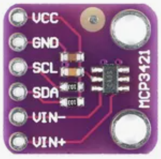
Pin Configuration and Descriptions

The MCP3421 is available in a 6-pin SOT-23 package. The pinout and descriptions are as follows:

Pin Name Type Description
1 VDD Power Positive power supply (2.7V to 5.5V).
2 VIN+ Analog Input Positive analog input for the ADC.
3 VIN- Analog Input Negative analog input for the ADC.
4 SCL Digital Input I2C clock line. Connect to the microcontroller's SCL pin.
5 SDA Digital I/O I2C data line. Connect to the microcontroller's SDA pin.
6 GND Power Ground reference for the device.

Usage Instructions

Connecting the MCP3421

  1. Power Supply: Connect the VDD pin to a 2.7V to 5.5V power source and the GND pin to ground.
  2. Analog Input: Connect the signal to be measured to the VIN+ pin. If measuring differential signals, connect the reference signal to the VIN- pin.
  3. I2C Interface:
    • Connect the SCL and SDA pins to the corresponding I2C pins on the microcontroller.
    • Use pull-up resistors (typically 4.7 kΩ) on the SCL and SDA lines.
  4. Addressing: The MCP3421 has a fixed I2C address of 0x68.

Example Circuit

Below is a basic connection diagram for the MCP3421 with an Arduino UNO:

MCP3421       Arduino UNO
---------     ------------
VDD           3.3V or 5V
GND           GND
SCL           A5 (SCL)
SDA           A4 (SDA)
VIN+          Signal Input
VIN-          Ground or Reference Signal

Arduino Code Example

The following Arduino code demonstrates how to read data from the MCP3421:

#include <Wire.h>

#define MCP3421_ADDRESS 0x68 // I2C address of the MCP3421

void setup() {
  Wire.begin(); // Initialize I2C communication
  Serial.begin(9600); // Initialize serial communication for debugging
}

void loop() {
  Wire.beginTransmission(MCP3421_ADDRESS);
  Wire.write(0x10); // Configuration byte: 18-bit resolution, PGA = 1x
  Wire.endTransmission();

  delay(100); // Wait for conversion to complete

  Wire.requestFrom(MCP3421_ADDRESS, 3); // Request 3 bytes of data
  if (Wire.available() == 3) {
    // Read the 3 bytes of data
    byte msb = Wire.read();
    byte lsb = Wire.read();
    byte config = Wire.read();

    // Combine the bytes into a 2's complement 18-bit value
    long rawData = ((long)msb << 16) | ((long)lsb << 8);
    rawData >>= 8; // Shift to remove the unused bits

    // Convert to voltage (assuming PGA = 1x and Vref = 2.048V)
    float voltage = (rawData * 2.048) / 131072.0;

    Serial.print("Voltage: ");
    Serial.print(voltage, 6); // Print voltage with 6 decimal places
    Serial.println(" V");
  }

  delay(1000); // Wait 1 second before the next reading
}

Important Considerations

  • Input Voltage Range: Ensure the input voltage does not exceed the specified range for the selected PGA setting.
  • I2C Pull-Up Resistors: Use appropriate pull-up resistors on the SCL and SDA lines to ensure reliable communication.
  • Noise Reduction: Minimize noise in the analog input signal by using proper grounding and shielding techniques.

Troubleshooting and FAQs

Common Issues

  1. No I2C Communication:

    • Verify the pull-up resistors on the SCL and SDA lines.
    • Check the wiring and ensure the correct I2C address (0x68) is used.
  2. Incorrect Voltage Readings:

    • Ensure the input voltage is within the specified range.
    • Verify the PGA setting and adjust the voltage calculation formula accordingly.
  3. Device Not Responding:

    • Confirm that the power supply voltage is within the 2.7V to 5.5V range.
    • Check for loose or incorrect connections.

FAQs

Q: Can the MCP3421 measure negative voltages?
A: Yes, the MCP3421 can measure differential signals, allowing it to measure negative voltages relative to the VIN- pin.

Q: What is the maximum sampling rate of the MCP3421?
A: The maximum sampling rate is 240 samples per second (SPS) at 12-bit resolution. At 18-bit resolution, the sampling rate is reduced to 3.75 SPS.

Q: Can I use the MCP3421 with a 3.3V microcontroller?
A: Yes, the MCP3421 operates with a supply voltage as low as 2.7V, making it compatible with 3.3V systems.

Q: How do I change the resolution or PGA settings?
A: The resolution and PGA settings are configured using the configuration byte sent via the I2C interface. Refer to the datasheet for details on the configuration byte format.