
How to Use Hall Effect Sensor: Examples, Pinouts, and Specs
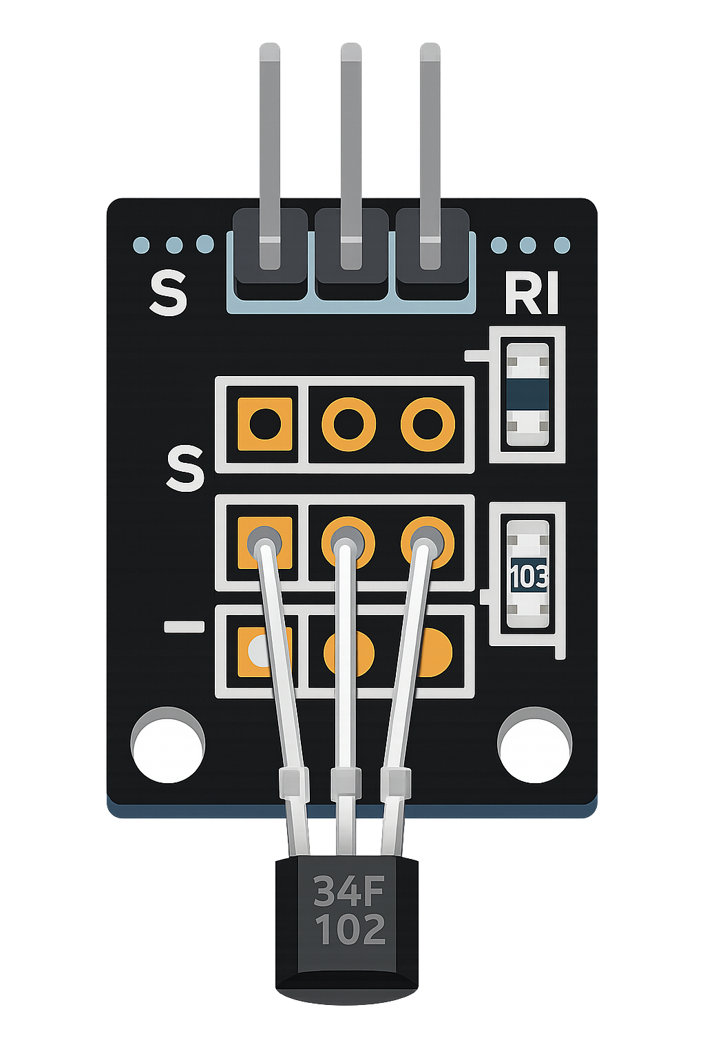
 Design with Hall Effect Sensor in Cirkit Designer
Introduction
A Hall Effect Sensor is a device that detects the presence and strength of a magnetic field. It operates based on the Hall effect principle, which generates a voltage proportional to the magnetic field strength when a current-carrying conductor is placed in a magnetic field. These sensors are widely used in various applications, including:
- Position sensing: Detecting the position of objects in industrial and automotive systems.
- Speed detection: Measuring the rotational speed of motors or wheels.
- Current sensing: Monitoring current flow in electrical circuits.
- Proximity sensing: Detecting the presence of nearby objects without physical contact.
Hall Effect Sensors are valued for their reliability, durability, and ability to operate in harsh environments.
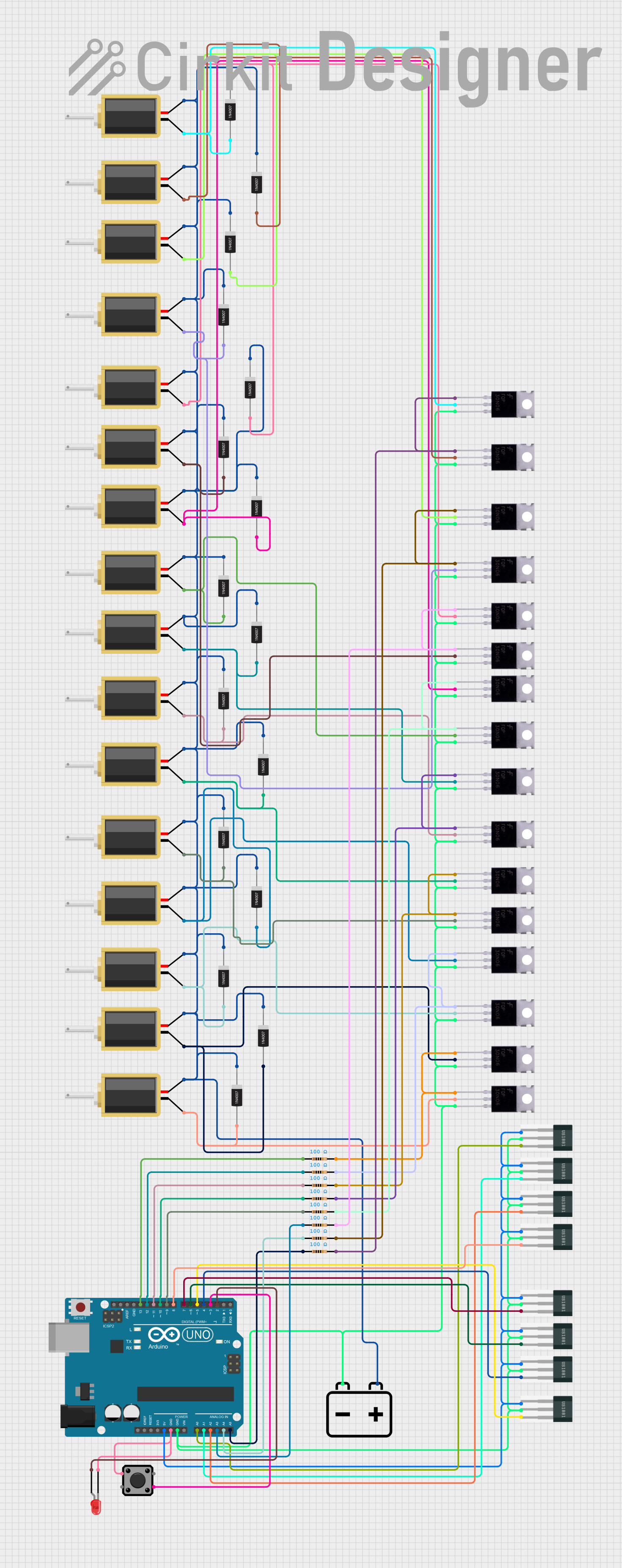
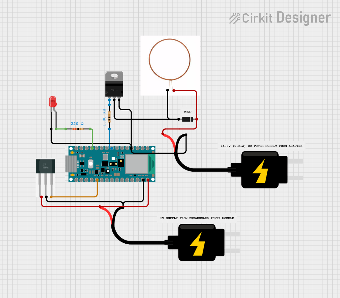
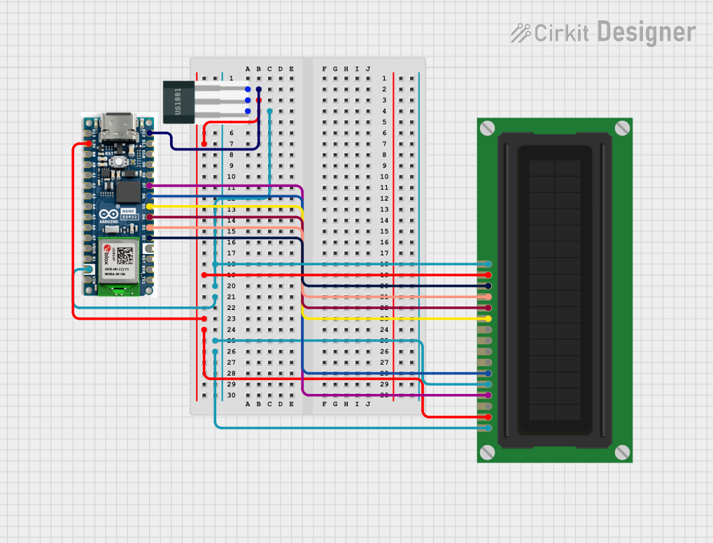
Explore Projects Built with Hall Effect Sensor
 Open Project in Cirkit Designer
 Open Project in Cirkit Designer
 Open Project in Cirkit Designer
 Open Project in Cirkit Designer
Explore Projects Built with Hall Effect Sensor
Open Project in Cirkit DesignerOpen Project in Cirkit DesignerOpen Project in Cirkit DesignerOpen Project in Cirkit DesignerTechnical Specifications
Below are the general technical specifications for a typical Hall Effect Sensor. Note that specific models may vary slightly in their ratings.
Key Specifications
- Operating Voltage: 3.3V to 5V DC
- Output Type: Digital or Analog (depending on the sensor model)
- Sensitivity: Varies by model (e.g., 1.4 mV/G for analog sensors)
- Operating Temperature Range: -40°C to 125°C
- Magnetic Field Range: ±50 mT to ±100 mT (typical)
- Response Time: <10 µs (for high-speed applications)
- Current Consumption: 5 mA (typical)
Pin Configuration and Descriptions
The pinout for a common 3-pin Hall Effect Sensor is as follows:
| Pin Number | Pin Name | Description |
|---|---|---|
| 1 | VCC | Power supply input (3.3V to 5V DC) |
| 2 | GND | Ground connection |
| 3 | OUT | Output signal (Digital HIGH/LOW or Analog voltage) |
Usage Instructions
How to Use the Component in a Circuit
- Power the Sensor: Connect the VCC pin to a 3.3V or 5V DC power supply and the GND pin to the ground of your circuit.
- Connect the Output: For digital sensors, the OUT pin will output a HIGH signal when a magnetic field is detected and LOW otherwise. For analog sensors, the OUT pin will provide a voltage proportional to the magnetic field strength.
- Place the Sensor: Position the sensor near the magnetic field source (e.g., a magnet or current-carrying conductor) for detection.
- Read the Output: Use a microcontroller (e.g., Arduino UNO) or a multimeter to monitor the output signal.
Important Considerations and Best Practices
- Magnetic Orientation: Ensure the magnetic field is perpendicular to the sensor for optimal detection.
- Noise Filtering: Use capacitors (e.g., 0.1 µF) across the power supply pins to reduce noise.
- Distance: Maintain an appropriate distance between the sensor and the magnetic source to avoid saturation or weak detection.
- Temperature: Operate the sensor within its specified temperature range to ensure accuracy and longevity.
Example: Connecting to an Arduino UNO
Below is an example of how to connect a digital Hall Effect Sensor to an Arduino UNO and read its output.
Circuit Connections
- Connect the VCC pin of the sensor to the 5V pin on the Arduino.
- Connect the GND pin of the sensor to the GND pin on the Arduino.
- Connect the OUT pin of the sensor to digital pin 2 on the Arduino.
Arduino Code
// Hall Effect Sensor Example with Arduino UNO
// This code reads the digital output of a Hall Effect Sensor and prints
// the status to the Serial Monitor.

const int hallSensorPin = 2; // Pin connected to the sensor's OUT pin
int sensorState = 0;         // Variable to store the sensor state

void setup() {
  pinMode(hallSensorPin, INPUT); // Set the sensor pin as input
  Serial.begin(9600);            // Initialize serial communication
}

void loop() {
  sensorState = digitalRead(hallSensorPin); // Read the sensor output

  if (sensorState == HIGH) {
    Serial.println("Magnetic field detected!"); // Print when field is detected
  } else {
    Serial.println("No magnetic field detected."); // Print when no field is detected
  }

  delay(500); // Wait for 500ms before reading again
}
Troubleshooting and FAQs
Common Issues and Solutions
No Output Signal:
- Cause: Incorrect wiring or insufficient power supply.
- Solution: Double-check the connections and ensure the sensor is powered with the correct voltage.
Inconsistent Readings:
- Cause: Electrical noise or unstable power supply.
- Solution: Add a decoupling capacitor (e.g., 0.1 µF) across the VCC and GND pins.
Sensor Not Detecting Magnetic Field:
- Cause: Magnetic field is too weak or improperly oriented.
- Solution: Use a stronger magnet or adjust the sensor's position to align with the magnetic field.
Output Always HIGH or LOW:
- Cause: Sensor saturation or damaged sensor.
- Solution: Reduce the magnetic field strength or replace the sensor if damaged.
FAQs
Q1: Can I use a Hall Effect Sensor to measure current?
A1: Yes, Hall Effect Sensors can measure current indirectly by detecting the magnetic field generated by a current-carrying conductor.
Q2: What is the difference between digital and analog Hall Effect Sensors?
A2: Digital sensors output a HIGH or LOW signal based on a threshold magnetic field, while analog sensors provide a continuous voltage proportional to the magnetic field strength.
Q3: Can Hall Effect Sensors detect non-magnetic materials?
A3: No, Hall Effect Sensors only respond to magnetic fields and cannot detect non-magnetic materials directly.
Q4: How do I increase the detection range of the sensor?
A4: Use a stronger magnet or a more sensitive Hall Effect Sensor model to increase the detection range.
By following this documentation, you can effectively integrate and troubleshoot a Hall Effect Sensor in your projects.