How to Use lora module: Examples, Pinouts, and Specs
Introduction
The HopeRF SX1278 is a LoRa (Long Range) module designed for low-power, long-range wireless communication. It operates using the LoRa modulation technique, which provides robust data transmission over extended distances while maintaining low power consumption. This makes it an ideal choice for Internet of Things (IoT) applications, remote sensing, and telemetry systems.
Explore Projects Built with lora module


Explore Projects Built with lora module
Common Applications and Use Cases
- Smart agriculture (e.g., soil moisture sensors, weather stations)
- Industrial IoT (e.g., machine monitoring, predictive maintenance)
- Smart cities (e.g., parking sensors, streetlight control)
- Home automation (e.g., security systems, energy monitoring)
- Environmental monitoring (e.g., air quality sensors, water level monitoring)
Technical Specifications
The SX1278 module is designed to operate in the 433 MHz ISM band (with some variants supporting 868 MHz or 915 MHz). Below are the key technical details:
Key Specifications
| Parameter | Value |
|---|---|
| Frequency Range | 137 MHz to 525 MHz |
| Modulation Technique | LoRa, FSK, GFSK, OOK |
| Output Power | Up to +20 dBm (100 mW) |
| Sensitivity | Down to -148 dBm |
| Data Rate | 0.018 kbps to 37.5 kbps |
| Supply Voltage | 1.8 V to 3.7 V |
| Current Consumption | 10.8 mA (Rx), 120 mA (Tx @ +20 dBm) |
| Communication Interface | SPI |
| Operating Temperature | -40°C to +85°C |
| Dimensions | 16 mm x 16 mm x 2 mm |
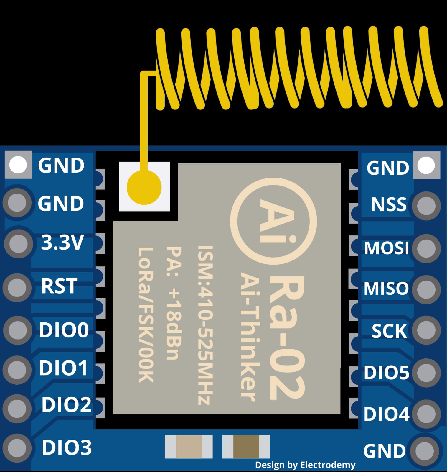
Pin Configuration and Descriptions
The SX1278 module typically has 16 pins. Below is the pinout and description:
| Pin Number | Pin Name | Description |
|---|---|---|
| 1 | GND | Ground |
| 2 | DIO0 | Digital I/O Pin 0 (Interrupt/Status) |
| 3 | DIO1 | Digital I/O Pin 1 (Interrupt/Status) |
| 4 | DIO2 | Digital I/O Pin 2 (Interrupt/Status) |
| 5 | DIO3 | Digital I/O Pin 3 (Interrupt/Status) |
| 6 | DIO4 | Digital I/O Pin 4 (Interrupt/Status) |
| 7 | DIO5 | Digital I/O Pin 5 (Interrupt/Status) |
| 8 | VCC | Power Supply (1.8 V to 3.7 V) |
| 9 | MISO | SPI Master In Slave Out |
| 10 | MOSI | SPI Master Out Slave In |
| 11 | SCK | SPI Clock |
| 12 | NSS | SPI Chip Select |
| 13 | RESET | Reset Pin (Active Low) |
| 14 | ANT | Antenna Connection |
| 15 | GND | Ground |
| 16 | NC | Not Connected |
Usage Instructions
How to Use the SX1278 in a Circuit
- Power Supply: Connect the VCC pin to a regulated power source (1.8 V to 3.7 V) and GND to ground.
- SPI Communication: Connect the SPI pins (MISO, MOSI, SCK, NSS) to the corresponding SPI pins on your microcontroller.
- Antenna: Attach a suitable 433 MHz antenna to the ANT pin for optimal performance.
- Reset: Use the RESET pin to initialize the module during startup.
- Digital I/O Pins: Use the DIO pins for interrupts or status monitoring as required by your application.
Important Considerations and Best Practices
- Antenna Matching: Ensure the antenna is properly matched to the operating frequency (433 MHz) for maximum range and efficiency.
- Power Supply: Use a stable and noise-free power supply to avoid communication issues.
- SPI Configuration: Configure the SPI interface on your microcontroller to match the SX1278's requirements (Mode 0 or Mode 3).
- Regulatory Compliance: Ensure compliance with local regulations for ISM band usage.
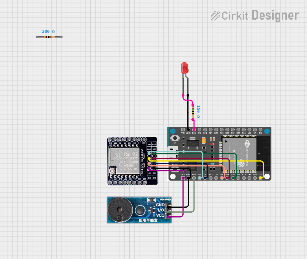
Example: Connecting SX1278 to Arduino UNO
Below is an example of how to connect the SX1278 to an Arduino UNO and send data using the LoRa library.
Wiring Diagram
| SX1278 Pin | Arduino UNO Pin |
|---|---|
| VCC | 3.3V |
| GND | GND |
| MISO | Pin 12 |
| MOSI | Pin 11 |
| SCK | Pin 13 |
| NSS | Pin 10 |
| RESET | Pin 9 |
| DIO0 | Pin 2 |
Arduino Code Example
#include <SPI.h>
#include <LoRa.h> // Include the LoRa library

#define NSS 10    // Chip select pin
#define RESET 9   // Reset pin
#define DIO0 2    // DIO0 pin

void setup() {
  Serial.begin(9600); // Initialize serial communication
  while (!Serial);

  // Initialize LoRa module
  LoRa.setPins(NSS, RESET, DIO0);
  if (!LoRa.begin(433E6)) { // Set frequency to 433 MHz
    Serial.println("LoRa initialization failed!");
    while (1);
  }
  Serial.println("LoRa initialized successfully.");
}

void loop() {
  Serial.println("Sending packet...");
  LoRa.beginPacket(); // Start a new packet
  LoRa.print("Hello, LoRa!"); // Add data to the packet
  LoRa.endPacket(); // Send the packet
  delay(5000); // Wait 5 seconds before sending the next packet
}
Troubleshooting and FAQs
Common Issues and Solutions
No Communication with the Module
- Solution: Verify SPI connections and ensure the NSS pin is correctly configured.
- Tip: Check the power supply voltage and ensure it is within the specified range (1.8 V to 3.7 V).
Poor Range or Signal Quality
- Solution: Ensure the antenna is properly connected and matched to the operating frequency.
- Tip: Avoid placing the module near sources of interference (e.g., Wi-Fi routers, motors).
LoRa Initialization Fails
- Solution: Double-check the wiring and ensure the correct frequency is set in the code.
- Tip: Use a logic analyzer or oscilloscope to debug SPI communication.
High Power Consumption
- Solution: Use the module's low-power modes when not actively transmitting or receiving.
- Tip: Refer to the datasheet for details on configuring sleep mode.
FAQs
Q: Can the SX1278 operate at 868 MHz or 915 MHz?
A: No, the SX1278 is specifically designed for the 433 MHz band. For 868 MHz or 915 MHz, consider using the SX1276 or SX1272.
Q: What is the maximum range of the SX1278?
A: The range depends on environmental factors, but it can achieve up to 10 km in open areas with a clear line of sight.
Q: Can I use the SX1278 with a 5V microcontroller?
A: Yes, but you must use a level shifter for the SPI pins, as the SX1278 operates at 3.3V logic levels.
Q: Is the SX1278 suitable for high-speed data transmission?
A: No, the SX1278 is optimized for low data rates (up to 37.5 kbps) to maximize range and reliability.