Cirkit Designer Logo
Cirkit Designer
Your all-in-one circuit design IDE
Home / 
Component Documentation

How to Use IEC320 In: Examples, Pinouts, and Specs

Image of IEC320 In
Cirkit Designer LogoDesign with IEC320 In in Cirkit Designer

Introduction

The IEC320 In, also known as the IEC C13 connector, is a standardized power connector commonly used in a variety of electrical appliances and equipment. It is designed to connect devices to the mains power supply, providing a secure and reliable connection for AC power. The IEC320 In is widely used in desktop computers, monitors, printers, and other office equipment, as well as in larger appliances like amplifiers and power distribution units.

Explore Projects Built with IEC320 In

Use Cirkit Designer to design, explore, and prototype these projects online. Some projects support real-time simulation. Click "Open Project" to start designing instantly!
ESP8266 NodeMCU Controlled SSR for Smart Power Management
Image of Copy of SISTEMA DE CONTROL POR DEMANDA DE DIOXIDO DE CARBONO: A project utilizing IEC320 In in a practical application
This circuit features an ESP8266 NodeMCU microcontroller that controls a solid-state relay to switch a 120V fan and a red lamp on and off. A green LED is used as an indicator for the relay's operation, and the circuit is powered by a 220V AC power source connected through an IEC320 inlet.
Cirkit Designer LogoOpen Project in Cirkit Designer
ESP32 and INA3221-Based Smart Power Monitoring System with Bluetooth and Environmental Sensing
Image of NMEA2000 Engine Interface: A project utilizing IEC320 In in a practical application
This circuit is a sensor monitoring and communication system that uses an ESP32 microcontroller to read data from a BME/BMP280 environmental sensor and an INA3221 power monitor. The ESP32 communicates with the sensors via I2C and transmits data wirelessly using an HC-05 Bluetooth module. Additionally, the circuit includes optocouplers and diodes for signal isolation and protection.
Cirkit Designer LogoOpen Project in Cirkit Designer
PID Temperature Control System with Thermocouple and SSR
Image of IR: A project utilizing IEC320 In in a practical application
This circuit is a temperature control system that uses a thermocouple to measure temperature and a PID controller to regulate it. The PID controller drives a solid-state relay (SSR) to control an external load, with power supplied through an AC inlet socket.
Cirkit Designer LogoOpen Project in Cirkit Designer
ESP32C3 and SIM800L Powered Smart Energy Monitor with OLED Display and Wi-Fi Connectivity
Image of master: A project utilizing IEC320 In in a practical application
This circuit is a power monitoring system that uses an ESP32C3 microcontroller to collect power usage data from slave devices via WiFi and SMS. The collected data is displayed on a 0.96" OLED screen, and the system is powered by an AC-DC converter module. Additionally, the circuit includes a SIM800L GSM module for SMS communication and LEDs for status indication.
Cirkit Designer LogoOpen Project in Cirkit Designer

Explore Projects Built with IEC320 In

Use Cirkit Designer to design, explore, and prototype these projects online. Some projects support real-time simulation. Click "Open Project" to start designing instantly!
Image of Copy of SISTEMA DE CONTROL POR DEMANDA DE DIOXIDO DE CARBONO: A project utilizing IEC320 In in a practical application
ESP8266 NodeMCU Controlled SSR for Smart Power Management
This circuit features an ESP8266 NodeMCU microcontroller that controls a solid-state relay to switch a 120V fan and a red lamp on and off. A green LED is used as an indicator for the relay's operation, and the circuit is powered by a 220V AC power source connected through an IEC320 inlet.
Cirkit Designer LogoOpen Project in Cirkit Designer
Image of NMEA2000 Engine Interface: A project utilizing IEC320 In in a practical application
ESP32 and INA3221-Based Smart Power Monitoring System with Bluetooth and Environmental Sensing
This circuit is a sensor monitoring and communication system that uses an ESP32 microcontroller to read data from a BME/BMP280 environmental sensor and an INA3221 power monitor. The ESP32 communicates with the sensors via I2C and transmits data wirelessly using an HC-05 Bluetooth module. Additionally, the circuit includes optocouplers and diodes for signal isolation and protection.
Cirkit Designer LogoOpen Project in Cirkit Designer
Image of IR: A project utilizing IEC320 In in a practical application
PID Temperature Control System with Thermocouple and SSR
This circuit is a temperature control system that uses a thermocouple to measure temperature and a PID controller to regulate it. The PID controller drives a solid-state relay (SSR) to control an external load, with power supplied through an AC inlet socket.
Cirkit Designer LogoOpen Project in Cirkit Designer
Image of master: A project utilizing IEC320 In in a practical application
ESP32C3 and SIM800L Powered Smart Energy Monitor with OLED Display and Wi-Fi Connectivity
This circuit is a power monitoring system that uses an ESP32C3 microcontroller to collect power usage data from slave devices via WiFi and SMS. The collected data is displayed on a 0.96" OLED screen, and the system is powered by an AC-DC converter module. Additionally, the circuit includes a SIM800L GSM module for SMS communication and LEDs for status indication.
Cirkit Designer LogoOpen Project in Cirkit Designer

Common Applications and Use Cases

  • Desktop computers and monitors
  • Printers and office machines
  • Amplifiers and audio equipment
  • Power distribution units in data centers
  • Laboratory and industrial equipment

Technical Specifications

Key Technical Details

  • Rated Voltage: Up to 250V AC
  • Rated Current: Up to 10A or 15A (depending on the specific model)
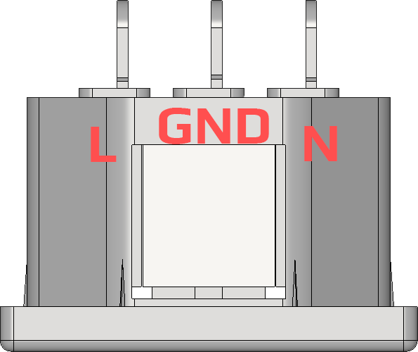
  • Number of Pins: 3 (including ground, live, and neutral)
  • Temperature Range: Typically -25°C to +70°C

Pin Configuration and Descriptions

Pin Number Description Wire Color (International)
1 Earth (Ground) Green/Yellow
2 Neutral Blue
3 Live (Hot) Brown or Black

Usage Instructions

How to Use the Component in a Circuit

  1. Power Source Connection: Ensure that the IEC320 In connector is properly connected to a compatible power source with the correct voltage and current ratings.
  2. Device Connection: Connect the IEC320 In to the corresponding IEC320 C14 male inlet on the device you wish to power.
  3. Safety Check: Before powering on the device, double-check all connections for proper polarity and secure fit.

Important Considerations and Best Practices

  • Polarity: Always connect the live, neutral, and ground wires to their respective pins as per the table above to avoid electrical hazards.
  • Cable Rating: Use a power cable that matches or exceeds the voltage and current ratings of the IEC320 In connector.
  • Inspection: Regularly inspect the connector for any signs of damage or wear. Replace if necessary.
  • Certification: Use connectors that are certified by recognized safety standards (e.g., UL, CE).

Troubleshooting and FAQs

Common Issues Users Might Face

  • Loose Connections: If the device intermittently powers off, check for loose connections at the IEC320 In and the power inlet.
  • Overheating: If the connector or cable is overheating, this may indicate an overcurrent condition. Disconnect the device and check the current rating of the appliance against the connector and cable.

Solutions and Tips for Troubleshooting

  • Secure Connections: Ensure that all connections are tight and secure. A loose connection can cause arcing and overheating.
  • Check Ratings: Verify that the power cable and connector are appropriately rated for the device's power requirements.
  • Visual Inspection: Look for signs of damage, such as melting or discoloration, which could indicate a serious issue.

FAQs

Q: Can I use the IEC320 In connector with any device? A: The IEC320 In connector should only be used with devices that have a compatible IEC320 C14 male inlet and are rated for the same voltage and current.

Q: Is it safe to plug in equipment that's rated for a different voltage? A: No, you should only use equipment that matches the power source's voltage to avoid damage or safety hazards.

Q: How can I tell if my IEC320 In connector is certified? A: Look for certification marks from recognized testing organizations (e.g., UL, CE) on the connector or packaging.


This documentation is intended to provide a comprehensive overview of the IEC320 In power connector. For specific applications or additional information, consult the manufacturer's datasheet or contact a professional electrician.