How to Use GT-U7 GPS Module: Examples, Pinouts, and Specs
Introduction
The GT-U7 GPS Module, manufactured by Deegoo-FPV, is a compact and efficient device designed to provide accurate positioning and timing information using GPS signals. It features a built-in ceramic antenna and supports multiple satellite navigation systems, ensuring reliable performance in various environments. The module is easy to integrate into electronic projects, making it a popular choice for applications such as navigation, vehicle tracking, drones, robotics, and other location-based services.
Explore Projects Built with GT-U7 GPS Module


Explore Projects Built with GT-U7 GPS Module
Common Applications:
- GPS navigation systems
- Vehicle and asset tracking
- Drones and UAVs
- Robotics and automation
- IoT devices requiring location data
- Time synchronization for embedded systems
Technical Specifications
Below are the key technical details of the GT-U7 GPS Module:
| Parameter | Specification |
|---|---|
| Manufacturer | Deegoo-FPV |
| Part Number | GT-U7 |
| Input Voltage | 3.3V to 5.0V |
| Operating Current | 20mA (typical) |
| Communication Interface | UART (default baud rate: 9600 bps) |
| Positioning Accuracy | 2.5 meters (CEP) |
| Cold Start Time | < 35 seconds |
| Warm Start Time | < 10 seconds |
| Hot Start Time | < 1 second |
| Antenna | Built-in ceramic antenna |
| Dimensions | 25mm x 25mm x 8mm |
| Operating Temperature | -40°C to +85°C |
| Supported Protocols | NMEA 0183, UBX |
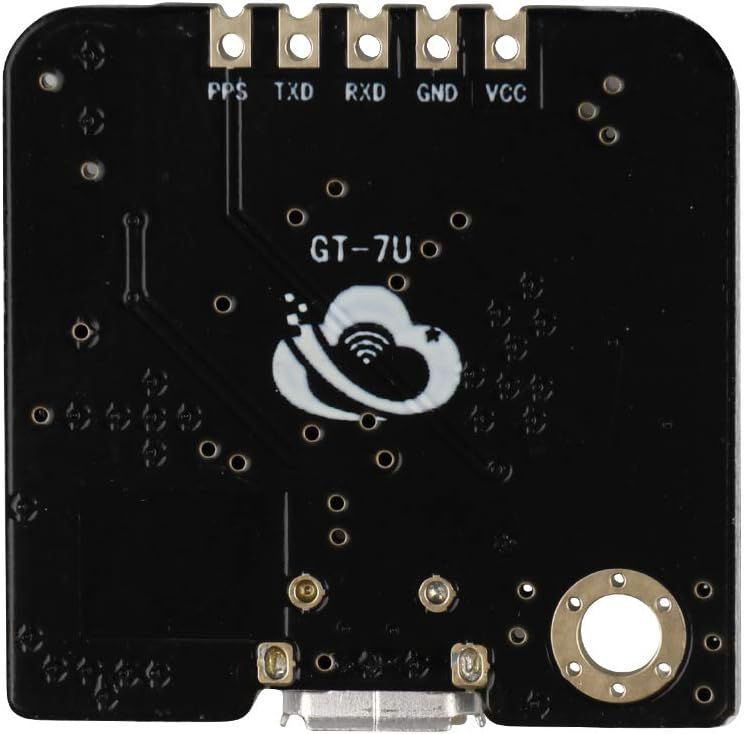
Pin Configuration and Descriptions
The GT-U7 GPS Module has a 4-pin interface for easy connection to microcontrollers and other devices. Below is the pinout:
| Pin | Name | Description |
|---|---|---|
| 1 | VCC | Power supply input (3.3V to 5.0V) |
| 2 | GND | Ground |
| 3 | TXD | UART Transmit (data output from the module) |
| 4 | RXD | UART Receive (data input to the module) |
Usage Instructions
Connecting the GT-U7 GPS Module
- Power Supply: Connect the
VCCpin to a 3.3V or 5.0V power source and theGNDpin to ground. - UART Communication:
- Connect the
TXDpin of the module to the RX pin of your microcontroller (e.g., Arduino UNO). - Connect the
RXDpin of the module to the TX pin of your microcontroller.
- Connect the
- Antenna Placement: Ensure the module's built-in antenna has a clear view of the sky for optimal GPS signal reception.
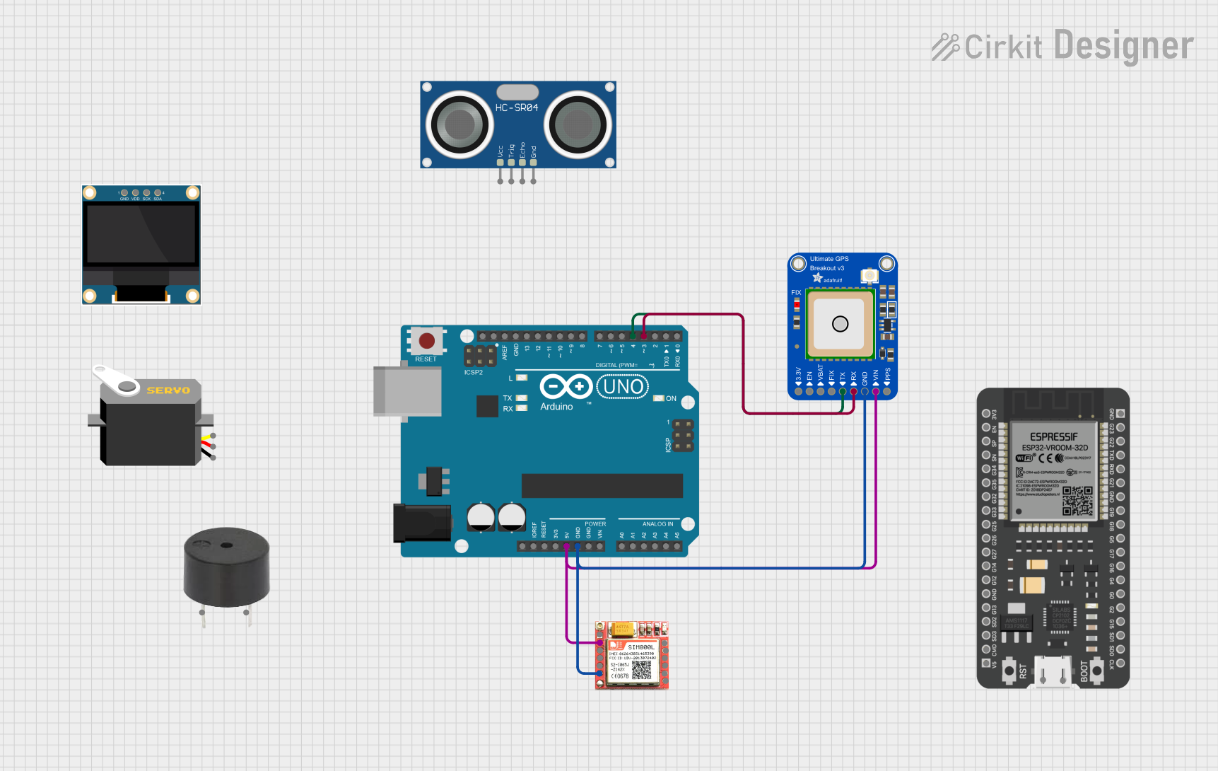
Example: Using GT-U7 with Arduino UNO
Below is an example of how to use the GT-U7 GPS Module with an Arduino UNO to read GPS data:
Circuit Diagram:
- Connect
VCCto the Arduino's5Vpin. - Connect
GNDto the Arduino'sGNDpin. - Connect
TXDto the Arduino'sRXpin (pin 0). - Connect
RXDto the Arduino'sTXpin (pin 1).
Arduino Code:
#include <SoftwareSerial.h>

// Create a SoftwareSerial object for communication with the GT-U7 GPS Module
SoftwareSerial gpsSerial(4, 3); // RX = pin 4, TX = pin 3

void setup() {
  Serial.begin(9600); // Initialize Serial Monitor at 9600 bps
  gpsSerial.begin(9600); // Initialize GPS module communication at 9600 bps

  Serial.println("GT-U7 GPS Module Test");
  Serial.println("Waiting for GPS data...");
}

void loop() {
  // Check if data is available from the GPS module
  while (gpsSerial.available()) {
    char c = gpsSerial.read(); // Read one character from the GPS module
    Serial.print(c); // Print the character to the Serial Monitor

    // Note: The GPS module outputs NMEA sentences, which can be parsed
    // for specific data like latitude, longitude, and time.
  }
}
Important Considerations:
- Baud Rate: The default baud rate of the GT-U7 is 9600 bps. Ensure your microcontroller's UART settings match this.
- Signal Reception: For best results, place the module outdoors or near a window with a clear view of the sky.
- Power Supply: Use a stable power source to avoid performance issues.
Troubleshooting and FAQs
Common Issues and Solutions:
No GPS Data Received:
- Ensure the module has a clear view of the sky.
- Verify the connections between the module and the microcontroller.
- Check that the baud rate is set correctly (default: 9600 bps).
Long Time to Acquire GPS Fix:
- This may occur during a cold start. Allow the module sufficient time to acquire satellite signals.
- Ensure the module is not obstructed by buildings, trees, or other objects.
Garbage Data in Serial Monitor:
- Verify that the baud rate in the Serial Monitor matches the baud rate of the GPS module.
- Check for loose or incorrect wiring.
Module Not Powering On:
- Confirm that the power supply voltage is within the specified range (3.3V to 5.0V).
- Check the connections to the
VCCandGNDpins.
FAQs:
Q1: Can the GT-U7 GPS Module be used indoors?
A1: While the module may work indoors, signal reception is significantly reduced. For best results, use the module outdoors or near a window.
Q2: How do I parse NMEA sentences from the module?
A2: NMEA sentences can be parsed using libraries like TinyGPS++ or by writing custom code to extract specific data fields.
Q3: Can I change the default baud rate of the module?
A3: Yes, the baud rate can be changed using specific UBX commands. Refer to the module's datasheet for details.
Q4: Does the module support other satellite systems like GLONASS?
A4: The GT-U7 primarily supports GPS signals. For multi-system support, check the module's datasheet or consider alternative models.
By following this documentation, you can effectively integrate the GT-U7 GPS Module into your projects and troubleshoot common issues.