How to Use RC SWITCH: Examples, Pinouts, and Specs
Introduction
An RC switch is a circuit component that utilizes a resistor (R) and a capacitor (C) to control the flow of current. By leveraging the charging and discharging characteristics of the capacitor, the RC switch can create time delays, filter signals, or shape waveforms in electronic circuits. This component is widely used in timing circuits, signal processing, and power management applications.
Explore Projects Built with RC SWITCH


Explore Projects Built with RC SWITCH
Common Applications and Use Cases
- Time Delay Circuits: Used to introduce a delay in the activation of a circuit.
- Signal Filtering: Acts as a low-pass or high-pass filter to remove unwanted frequencies.
- Debouncing: Helps stabilize signals from mechanical switches.
- Waveform Shaping: Smooths or modifies signal waveforms in analog circuits.
- Power Supply Circuits: Used for soft-start mechanisms to prevent inrush current.
Technical Specifications
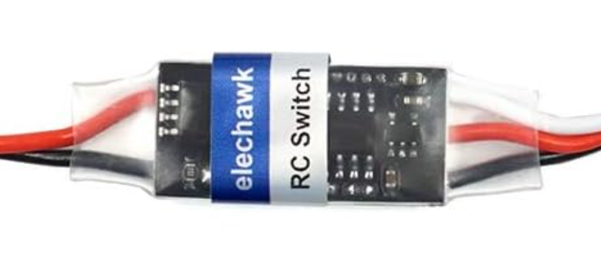
Below are the key technical details for the RC switch with part ID 4A 15V:
General Specifications
- Resistor Value (R): User-defined, typically in the range of 1 kΩ to 1 MΩ.
- Capacitor Value (C): User-defined, typically in the range of 1 nF to 100 µF.
- Maximum Voltage: 15 V
- Maximum Current: 4 A
- Operating Temperature Range: -40°C to +85°C
- Power Dissipation: Dependent on resistor and capacitor ratings.
Pin Configuration and Descriptions
The RC switch is typically implemented as a circuit rather than a discrete component. However, for modular RC switch modules, the pin configuration is as follows:
| Pin | Name | Description |
|---|---|---|
| 1 | Input (Vin) | Input voltage to the RC switch circuit. |
| 2 | Output (Vout) | Output voltage after the RC circuit processes the input signal. |
| 3 | Ground (GND) | Common ground connection for the circuit. |
| 4 | Control (CTRL) | Optional control pin to enable or disable the RC switch functionality (if available). |
Usage Instructions
How to Use the RC Switch in a Circuit
Determine the Desired Time Constant:
- The time constant (τ) is calculated as
τ = R × C, whereRis the resistance in ohms andCis the capacitance in farads. - Choose appropriate resistor and capacitor values based on the required delay or filtering characteristics.
- The time constant (τ) is calculated as
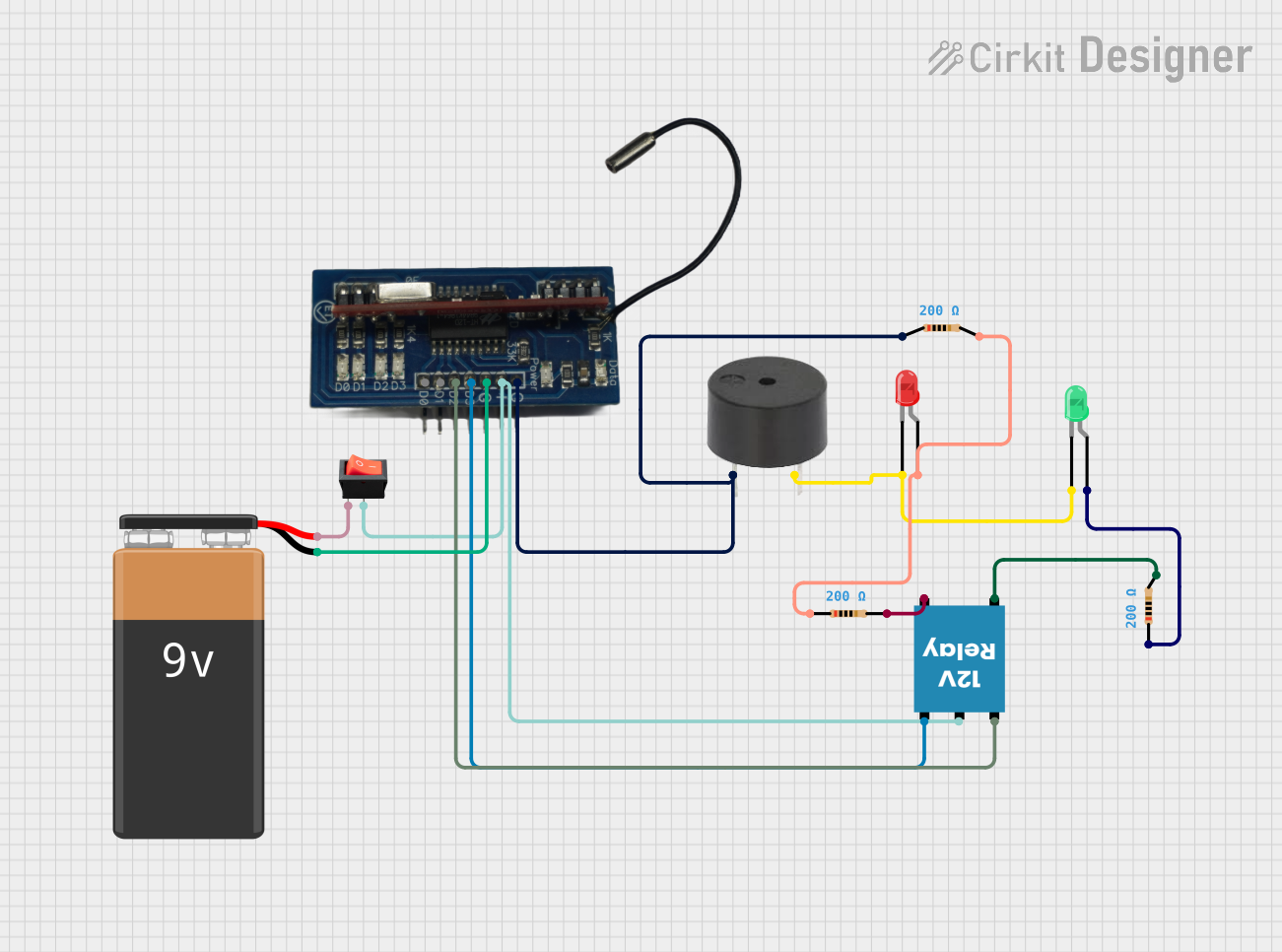
Connect the RC Circuit:
- Connect the resistor and capacitor in series for a basic RC switch.
- Attach the input signal to the resistor and the output signal to the junction between the resistor and capacitor.
Power the Circuit:
- Ensure the input voltage does not exceed the maximum voltage rating of 15 V.
- Connect the ground pin to the common ground of the circuit.
Optional Control Pin:
- If the RC switch module includes a control pin, use it to enable or disable the circuit as needed.
Important Considerations and Best Practices
- Component Ratings: Ensure the resistor and capacitor can handle the voltage and current levels in your circuit.
- Leakage Current: Be aware of capacitor leakage, which can affect the time constant over long periods.
- Signal Compatibility: Verify that the RC switch is suitable for the frequency range of your input signal.
- Heat Dissipation: Use resistors with adequate power ratings to prevent overheating.
Example: Using an RC Switch with Arduino UNO
Below is an example of using an RC switch to create a time delay for an LED connected to an Arduino UNO:
// Define the pin for the LED
const int ledPin = 9; // LED connected to digital pin 9

void setup() {
  pinMode(ledPin, OUTPUT); // Set the LED pin as an output
}

void loop() {
  digitalWrite(ledPin, HIGH); // Turn the LED on
  delay(1000); // Wait for 1 second (RC delay can be added here)
  digitalWrite(ledPin, LOW); // Turn the LED off
  delay(1000); // Wait for 1 second
}
Note: The RC switch can be connected between the Arduino output pin and the LED to introduce an additional delay or to smooth the signal.
Troubleshooting and FAQs
Common Issues and Solutions
No Output Signal:
- Cause: Incorrect resistor or capacitor values.
- Solution: Recalculate the time constant and verify the component values.
Signal Distortion:
- Cause: The RC circuit is not suitable for the input signal frequency.
- Solution: Adjust the resistor and capacitor values to match the desired frequency range.
Overheating Components:
- Cause: Resistor power rating is too low.
- Solution: Use a resistor with a higher power rating.
Capacitor Leakage:
- Cause: Aging or low-quality capacitor.
- Solution: Replace the capacitor with a new one of the same or higher quality.
FAQs
Q: Can I use an RC switch for AC signals?
- A: Yes, RC switches can be used for AC signals, but the component values must be chosen to match the signal frequency.
Q: How do I calculate the cutoff frequency for an RC filter?
- A: The cutoff frequency is calculated as
f_c = 1 / (2πRC), whereRis the resistance in ohms andCis the capacitance in farads.
- A: The cutoff frequency is calculated as
Q: Can I use an RC switch for high-power applications?
- A: RC switches are generally not suitable for high-power applications. Use components rated for the required power levels.
By following this documentation, you can effectively use the RC switch in your electronic projects.