How to Use BTS 7960 Motor Drver 43a: Examples, Pinouts, and Specs
Introduction
The BTS 7960 Motor Driver, manufactured by Infineon Technologies (Part ID: B0D732VYGZ), is a high-current motor driver designed for controlling DC motors with a maximum continuous current of 43A. This robust H-bridge driver integrates advanced protection features, including overcurrent and thermal overload safeguards, making it ideal for high-power motor control applications.
Explore Projects Built with BTS 7960 Motor Drver 43a

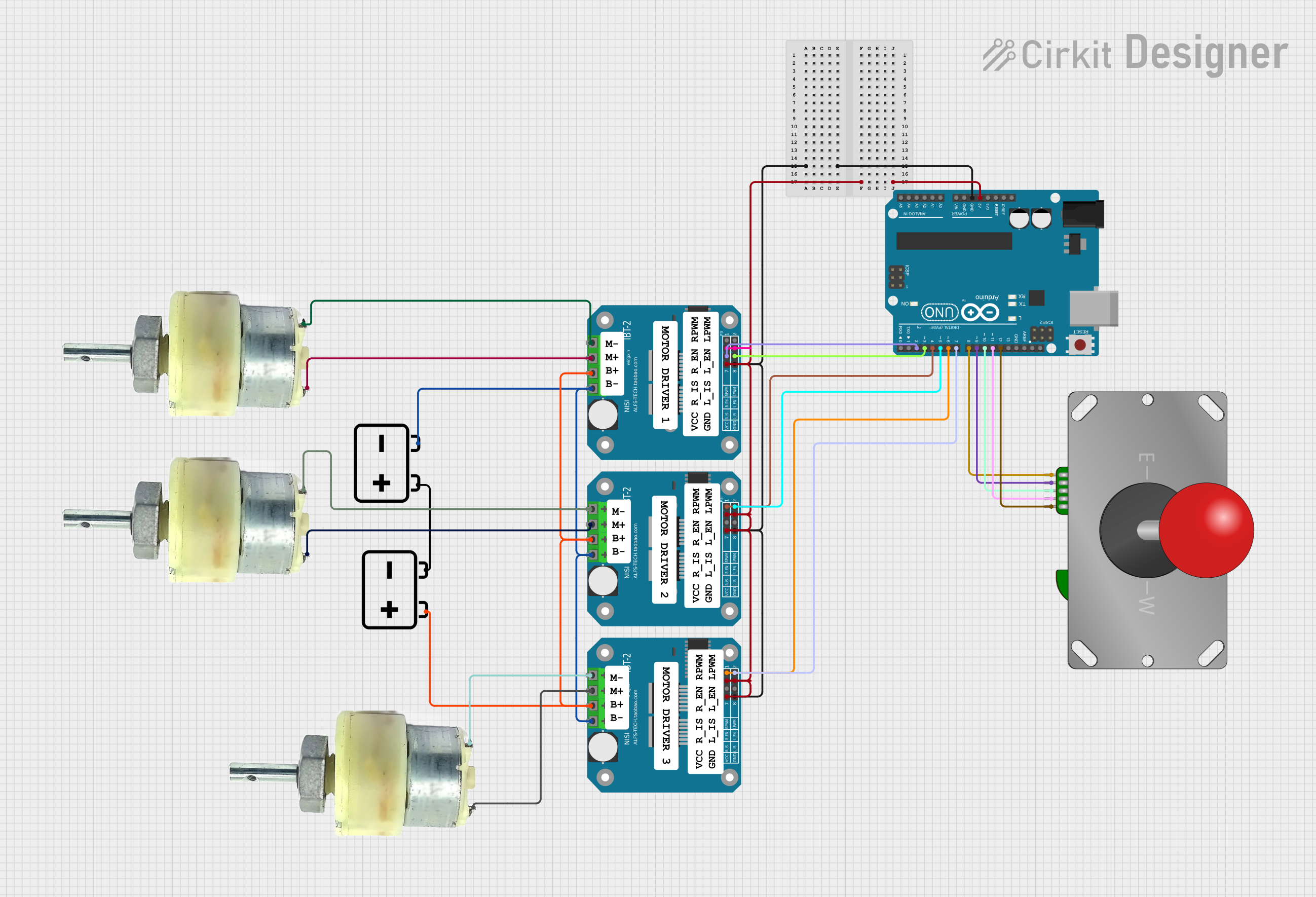
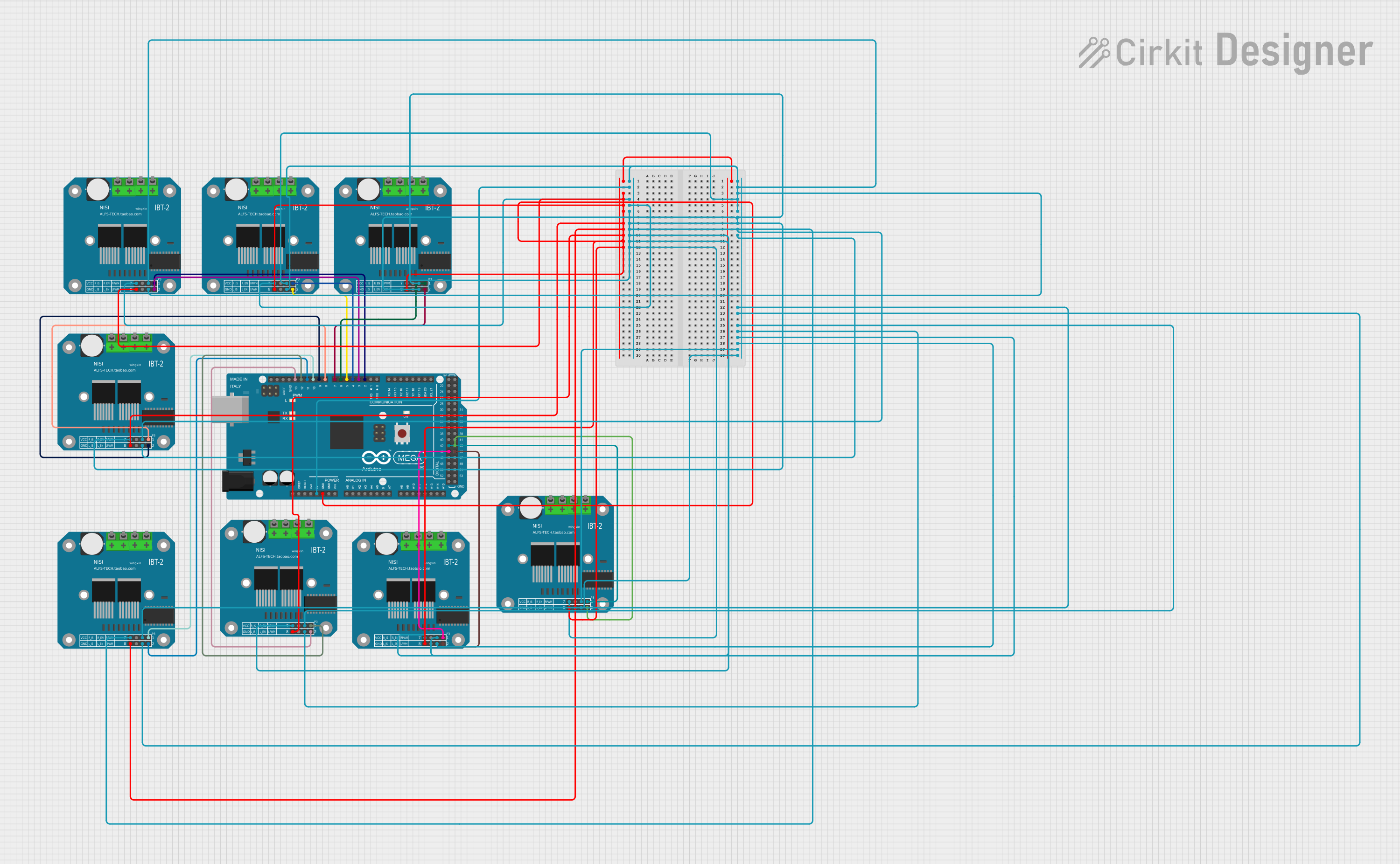
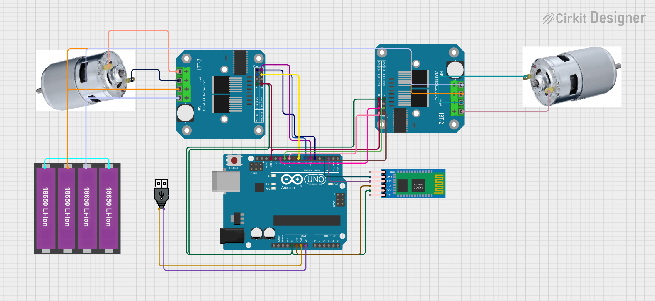
Explore Projects Built with BTS 7960 Motor Drver 43a
Common Applications and Use Cases
- Robotics and automation systems
- Electric vehicles and e-bikes
- Conveyor belts and industrial machinery
- High-power RC vehicles
- Smart home devices requiring motorized control
Technical Specifications
The BTS 7960 is a dual high-side and low-side MOSFET driver with integrated protection features. Below are its key technical details:
Key Technical Details
| Parameter | Value |
|---|---|
| Operating Voltage Range | 5.5V to 27V |
| Maximum Continuous Current | 43A |
| Peak Current | 50A |
| PWM Frequency | Up to 25kHz |
| Logic Input Voltage | 3.3V or 5V (TTL compatible) |
| Overcurrent Protection | Yes |
| Thermal Shutdown | Yes |
| Dimensions | 4.5cm x 5.5cm (approx.) |
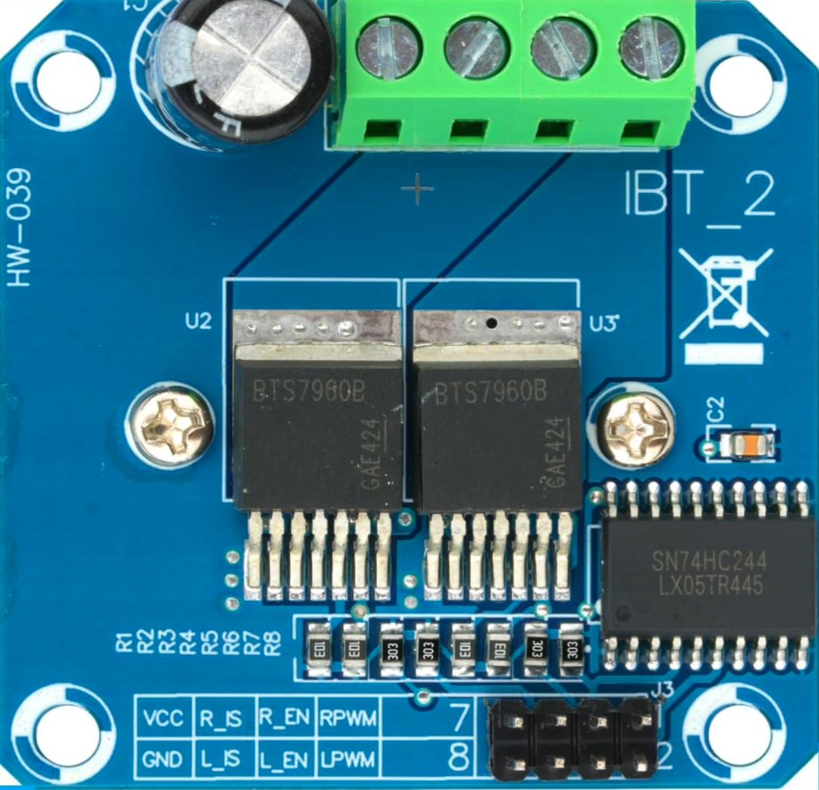
Pin Configuration and Descriptions
The BTS 7960 module typically features the following pinout:
| Pin Name | Description |
|---|---|
| VCC | Power supply for the motor driver (5.5V to 27V). |
| GND | Ground connection. |
| RPWM | Right PWM input signal for controlling motor direction and speed. |
| LPWM | Left PWM input signal for controlling motor direction and speed. |
| R_EN | Enable pin for the right side of the H-bridge. |
| L_EN | Enable pin for the left side of the H-bridge. |
| IS | Current sensing output (optional, for monitoring motor current). |
| Motor+ | Positive terminal of the motor. |
| Motor- | Negative terminal of the motor. |
Usage Instructions
How to Use the BTS 7960 in a Circuit
- Power Supply: Connect the VCC pin to a power source within the range of 5.5V to 27V. Ensure the power supply can handle the motor's current requirements.
- Motor Connection: Attach the motor terminals to the Motor+ and Motor- pins.
- Logic Inputs: Connect the RPWM and LPWM pins to a microcontroller (e.g., Arduino) to control motor speed and direction using PWM signals.
- Enable Pins: Set the R_EN and L_EN pins HIGH to enable the respective sides of the H-bridge.
- Grounding: Ensure all grounds (GND) are connected to a common ground in the circuit.
Important Considerations and Best Practices
- Use a heat sink or active cooling for the BTS 7960 module when operating at high currents to prevent thermal shutdown.
- Add appropriate decoupling capacitors near the VCC pin to reduce voltage ripple.
- Ensure the motor's stall current does not exceed the module's peak current rating (50A).
- Use fuses or circuit breakers for additional protection in high-current applications.
Example Code for Arduino UNO
Below is an example of how to control a DC motor using the BTS 7960 with an Arduino UNO:
// Define pin connections for the BTS 7960 motor driver
const int RPWM = 5;  // Right PWM pin connected to Arduino pin 5
const int LPWM = 6;  // Left PWM pin connected to Arduino pin 6
const int R_EN = 7;  // Right enable pin connected to Arduino pin 7
const int L_EN = 8;  // Left enable pin connected to Arduino pin 8

void setup() {
  // Set motor driver pins as outputs
  pinMode(RPWM, OUTPUT);
  pinMode(LPWM, OUTPUT);
  pinMode(R_EN, OUTPUT);
  pinMode(L_EN, OUTPUT);

  // Enable both sides of the H-bridge
  digitalWrite(R_EN, HIGH);
  digitalWrite(L_EN, HIGH);
}

void loop() {
  // Rotate motor in one direction
  analogWrite(RPWM, 200);  // Set speed (0-255)
  analogWrite(LPWM, 0);    // Ensure opposite side is off
  delay(2000);             // Run for 2 seconds

  // Stop the motor
  analogWrite(RPWM, 0);
  analogWrite(LPWM, 0);
  delay(1000);             // Pause for 1 second

  // Rotate motor in the opposite direction
  analogWrite(RPWM, 0);
  analogWrite(LPWM, 200);  // Set speed (0-255)
  delay(2000);             // Run for 2 seconds

  // Stop the motor
  analogWrite(RPWM, 0);
  analogWrite(LPWM, 0);
  delay(1000);             // Pause for 1 second
}
Troubleshooting and FAQs
Common Issues and Solutions
Motor Not Spinning:
- Ensure the power supply voltage is within the specified range (5.5V to 27V).
- Verify that the R_EN and L_EN pins are set HIGH to enable the H-bridge.
- Check the PWM signal connections (RPWM and LPWM) from the microcontroller.
Overheating:
- Use a heat sink or active cooling to dissipate heat during high-current operation.
- Reduce the motor's load or duty cycle to lower the current draw.
Erratic Motor Behavior:
- Ensure all ground connections are properly connected.
- Add decoupling capacitors near the VCC pin to stabilize the power supply.
No Current Sensing Output:
- Verify the IS pin connection and ensure it is properly configured for monitoring.
FAQs
Q: Can the BTS 7960 handle brushless DC motors?
A: No, the BTS 7960 is designed for brushed DC motors. For brushless motors, consider using a dedicated brushless motor driver.
Q: What is the maximum PWM frequency supported?
A: The BTS 7960 supports PWM frequencies up to 25kHz.
Q: Can I use the BTS 7960 with a 3.3V microcontroller?
A: Yes, the logic inputs (RPWM, LPWM, R_EN, L_EN) are compatible with both 3.3V and 5V logic levels.
Q: Is reverse polarity protection included?
A: No, the BTS 7960 does not have built-in reverse polarity protection. Use an external diode for protection if needed.