How to Use Full Bridge Rectifier: Examples, Pinouts, and Specs
Introduction
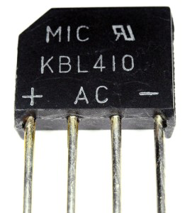
The KBL410 Full Bridge Rectifier, manufactured by MIC, is a compact and efficient component designed to convert alternating current (AC) into direct current (DC). It utilizes four diodes arranged in a bridge configuration, enabling the rectification of both halves of the AC waveform. This design ensures higher efficiency and smoother DC output compared to half-wave rectifiers.
Explore Projects Built with Full Bridge Rectifier
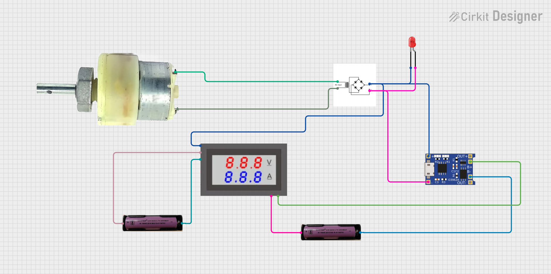
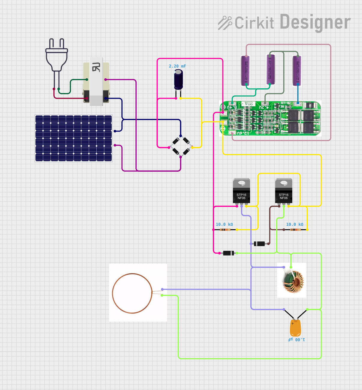

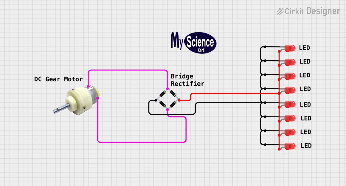
Explore Projects Built with Full Bridge Rectifier
Common Applications and Use Cases
- Power supplies for electronic devices
- Battery charging circuits
- DC motor drives
- LED lighting systems
- Industrial control systems
Technical Specifications
The KBL410 Full Bridge Rectifier is designed for robust performance in a variety of applications. Below are its key technical specifications:
| Parameter | Value |
|---|---|
| Manufacturer | MIC |
| Part Number | KBL410 |
| Maximum Repetitive Peak Reverse Voltage (VRRM) | 1000V |
| Maximum Average Forward Rectified Current (IF(AV)) | 4A |
| Peak Forward Surge Current (IFSM) | 150A |
| Forward Voltage Drop (VF) | 1.1V (per diode) |
| Operating Temperature Range | -55°C to +150°C |
| Package Type | KBL (4-pin rectangular package) |
Pin Configuration and Descriptions
The KBL410 has four pins, as described in the table below:
| Pin Number | Pin Name | Description |
|---|---|---|
| 1 | AC Input 1 | First AC input terminal |
| 2 | AC Input 2 | Second AC input terminal |
| 3 | DC Output (+) | Positive DC output terminal |
| 4 | DC Output (-) | Negative DC output terminal (ground) |
Usage Instructions
How to Use the KBL410 in a Circuit
- Connect the AC Input Terminals: Attach the AC voltage source to the two AC input pins (Pin 1 and Pin 2). Ensure the input voltage does not exceed the maximum repetitive peak reverse voltage (1000V).
- Connect the DC Output Terminals: Connect the positive DC output terminal (Pin 3) to the load's positive terminal and the negative DC output terminal (Pin 4) to the load's ground.
- Add a Filter Capacitor (Optional): To smooth the rectified DC output, connect a capacitor across the DC output terminals. The capacitor value depends on the desired ripple voltage and load current.
Important Considerations and Best Practices
- Heat Dissipation: Ensure adequate heat dissipation by mounting the rectifier on a heatsink if operating near its maximum current rating.
- Input Voltage: Verify that the input AC voltage is within the rectifier's voltage rating.
- Polarity: Double-check the polarity of the DC output connections to avoid damage to the load.
- Fuse Protection: Use a fuse on the AC input side to protect the rectifier and circuit from overcurrent conditions.
Example: Using the KBL410 with an Arduino UNO
The KBL410 can be used to power an Arduino UNO by rectifying an AC voltage source and providing a stable DC voltage. Below is an example circuit and code:
Circuit Description
- Connect a 12V AC transformer to the AC input terminals of the KBL410.
- Add a 1000µF capacitor across the DC output terminals to smooth the DC voltage.
- Use a 7805 voltage regulator to step down the rectified DC voltage to 5V for the Arduino UNO.
Arduino Code Example
// Example code to blink an LED using an Arduino UNO powered by the KBL410
// Full Bridge Rectifier. Ensure the rectified DC voltage is regulated to 5V.

const int ledPin = 13; // Pin connected to the onboard LED

void setup() {
  pinMode(ledPin, OUTPUT); // Set the LED pin as an output
}

void loop() {
  digitalWrite(ledPin, HIGH); // Turn the LED on
  delay(1000);                // Wait for 1 second
  digitalWrite(ledPin, LOW);  // Turn the LED off
  delay(1000);                // Wait for 1 second
}
Troubleshooting and FAQs
Common Issues and Solutions
No DC Output:
- Cause: Incorrect wiring of the AC input or DC output terminals.
- Solution: Verify the connections using the pin configuration table.
Excessive Heat:
- Cause: Operating near or above the maximum current rating without proper heat dissipation.
- Solution: Attach a heatsink to the rectifier and ensure adequate ventilation.
High Ripple Voltage:
- Cause: Insufficient filtering of the rectified DC output.
- Solution: Increase the value of the filter capacitor or use a voltage regulator.
Blown Fuse:
- Cause: Overcurrent due to a short circuit or excessive load.
- Solution: Check the circuit for shorts and ensure the load current is within the rectifier's rating.
FAQs
Q1: Can the KBL410 handle 50Hz and 60Hz AC input?
A1: Yes, the KBL410 is compatible with both 50Hz and 60Hz AC input frequencies.
Q2: What is the maximum DC output voltage of the KBL410?
A2: The maximum DC output voltage is approximately the peak value of the AC input voltage minus the forward voltage drop of the diodes (1.1V per diode).
Q3: Can I use the KBL410 for three-phase AC rectification?
A3: No, the KBL410 is designed for single-phase AC rectification. For three-phase rectification, use a three-phase bridge rectifier.
Q4: Is the KBL410 suitable for high-frequency AC input?
A4: The KBL410 is optimized for low-frequency AC input (50Hz/60Hz). For high-frequency applications, consider using a fast recovery or Schottky diode bridge rectifier.
By following this documentation, users can effectively integrate the KBL410 Full Bridge Rectifier into their electronic projects and troubleshoot common issues with ease.