
How to Use PZEM-004T 100A: Examples, Pinouts, and Specs
 Design with PZEM-004T 100A in Cirkit Designer
Introduction
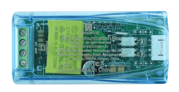
The PZEM-004T 100A is a multifunctional energy meter designed for monitoring and managing electrical parameters in AC circuits. It measures key metrics such as voltage, current, power, energy, and frequency, providing real-time data through a serial communication interface. With its ability to handle up to 100A of current, this module is ideal for applications requiring precise energy monitoring.
Explore Projects Built with PZEM-004T 100A
 Open Project in Cirkit Designer
 Open Project in Cirkit Designer
 Open Project in Cirkit Designer
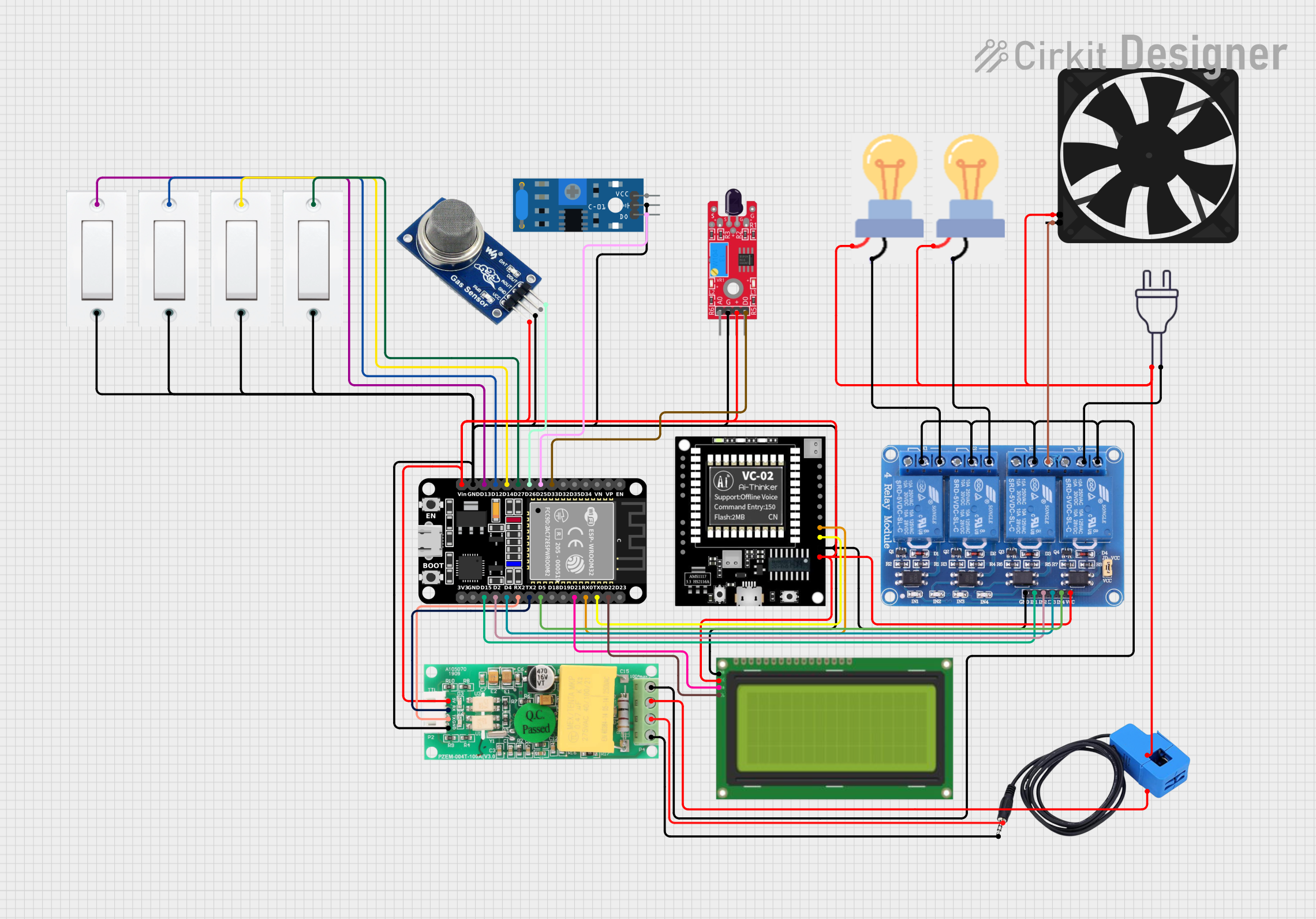 Open Project in Cirkit Designer
Explore Projects Built with PZEM-004T 100A
Open Project in Cirkit DesignerOpen Project in Cirkit DesignerOpen Project in Cirkit DesignerOpen Project in Cirkit DesignerCommon Applications
- Home energy monitoring systems
- Industrial equipment power management
- Renewable energy systems (e.g., solar inverters)
- Smart IoT-based energy monitoring solutions
- Electrical load analysis in laboratories
Technical Specifications
Below are the key technical details of the PZEM-004T 100A module:
| Parameter | Specification |
|---|---|
| Voltage Range | 80V - 260V AC |
| Current Range | 0A - 100A (with external CT sensor) |
| Power Range | 0W - 22kW |
| Energy Range | 0kWh - 9999kWh |
| Frequency Range | 45Hz - 65Hz |
| Communication Interface | TTL Serial (3.3V/5V compatible) |
| Baud Rate | 9600 bps |
| Accuracy | ±0.5% |
| Operating Temperature | -10°C to 60°C |
| Dimensions | 48mm x 29mm x 22mm |
Pin Configuration
The PZEM-004T 100A module has a 4-pin interface for power and communication. The pinout is as follows:
| Pin | Name | Description |
|---|---|---|
| 1 | VCC | Power supply input (5V DC) |
| 2 | GND | Ground connection |
| 3 | RX | Serial data receive pin (connect to TX of MCU) |
| 4 | TX | Serial data transmit pin (connect to RX of MCU) |
Additionally, the module includes an external current transformer (CT) sensor for current measurement.
Usage Instructions
Connecting the PZEM-004T 100A
- Power Supply: Connect the VCC pin to a 5V DC power source and the GND pin to ground.
- Serial Communication: Connect the RX pin of the module to the TX pin of your microcontroller (e.g., Arduino UNO) and the TX pin of the module to the RX pin of the microcontroller.
- Current Transformer (CT): Place the CT sensor around the live wire of the AC circuit you want to monitor. Ensure the arrow on the CT sensor aligns with the current flow direction.
- Voltage Measurement: Connect the AC voltage input terminals of the module to the live and neutral wires of the circuit.
Important Considerations
- Isolation: Ensure proper electrical isolation between the module and high-voltage AC circuits to avoid damage or safety hazards.
- CT Sensor Placement: The CT sensor should only clamp around one conductor (live wire) and not both live and neutral wires.
- Baud Rate: The module communicates at a fixed baud rate of 9600 bps. Ensure your microcontroller is configured accordingly.
- Power Supply: Use a stable 5V DC power source to avoid communication errors or inaccurate readings.
Example Code for Arduino UNO
Below is an example Arduino sketch to interface with the PZEM-004T 100A module:
#include <SoftwareSerial.h>

// Define RX and TX pins for SoftwareSerial
SoftwareSerial pzemSerial(10, 11); // RX = Pin 10, TX = Pin 11

// PZEM-004T communication commands
byte readCommand[] = {0xB0, 0xC0, 0xA8, 0x01, 0x01, 0x00, 0x1A};

// Function to send a command to the PZEM-004T
void sendCommand(byte *command, int length) {
  for (int i = 0; i < length; i++) {
    pzemSerial.write(command[i]);
  }
}

void setup() {
  Serial.begin(9600);          // Initialize Serial Monitor
  pzemSerial.begin(9600);      // Initialize SoftwareSerial for PZEM-004T
  Serial.println("PZEM-004T Test");
}

void loop() {
  sendCommand(readCommand, sizeof(readCommand)); // Send read command
  delay(100); // Wait for response

  // Check if data is available from the PZEM-004T
  if (pzemSerial.available()) {
    Serial.print("Data received: ");
    while (pzemSerial.available()) {
      byte data = pzemSerial.read();
      Serial.print(data, HEX); // Print data in hexadecimal format
      Serial.print(" ");
    }
    Serial.println();
  }

  delay(1000); // Wait 1 second before next read
}
Notes on the Code
- The
readCommandarray contains a sample command to request data from the PZEM-004T. Modify it as needed based on your specific requirements. - Use pins 10 and 11 for SoftwareSerial communication, but these can be changed if necessary.
- Ensure the Arduino and PZEM-004T share a common ground.
Troubleshooting and FAQs
Common Issues
No Data Received
- Ensure the RX and TX pins are correctly connected between the module and the microcontroller.
- Verify the baud rate is set to 9600 bps in your code.
- Check the power supply to the module (5V DC).
Inaccurate Readings
- Confirm the CT sensor is properly clamped around the live wire.
- Ensure the CT sensor is not damaged or loosely connected.
- Verify the AC voltage input terminals are securely connected.
Communication Errors
- Check for loose or incorrect wiring between the module and the microcontroller.
- Ensure the microcontroller and module share a common ground.
FAQs
Q: Can the PZEM-004T measure DC circuits?
A: No, the PZEM-004T is designed specifically for AC circuits and cannot measure DC voltage or current.
Q: Can I extend the CT sensor cable?
A: Yes, but ensure the extension does not introduce significant resistance or noise, which could affect accuracy.
Q: Is the module compatible with 3.3V microcontrollers?
A: Yes, the TTL serial interface is compatible with both 3.3V and 5V logic levels.
Q: How do I reset the energy counter?
A: The energy counter can be reset by sending a specific command via the serial interface. Refer to the module's datasheet for details.
By following this documentation, you can effectively integrate the PZEM-004T 100A into your projects for accurate energy monitoring and management.