How to Use Chopper Logics Board: Examples, Pinouts, and Specs
Introduction
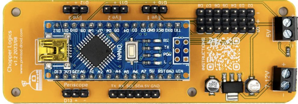
The Chopper Logics Board by Printed-Droids.net (Part ID: Chopper Logics Board) is a specialized circuit board designed to manage and control the operation of chopper circuits. Chopper circuits are widely used in applications requiring efficient DC voltage conversion, such as motor drives, power supplies, and renewable energy systems. This board integrates logic components for signal processing and control, ensuring precise and reliable performance in demanding environments.
Explore Projects Built with Chopper Logics Board
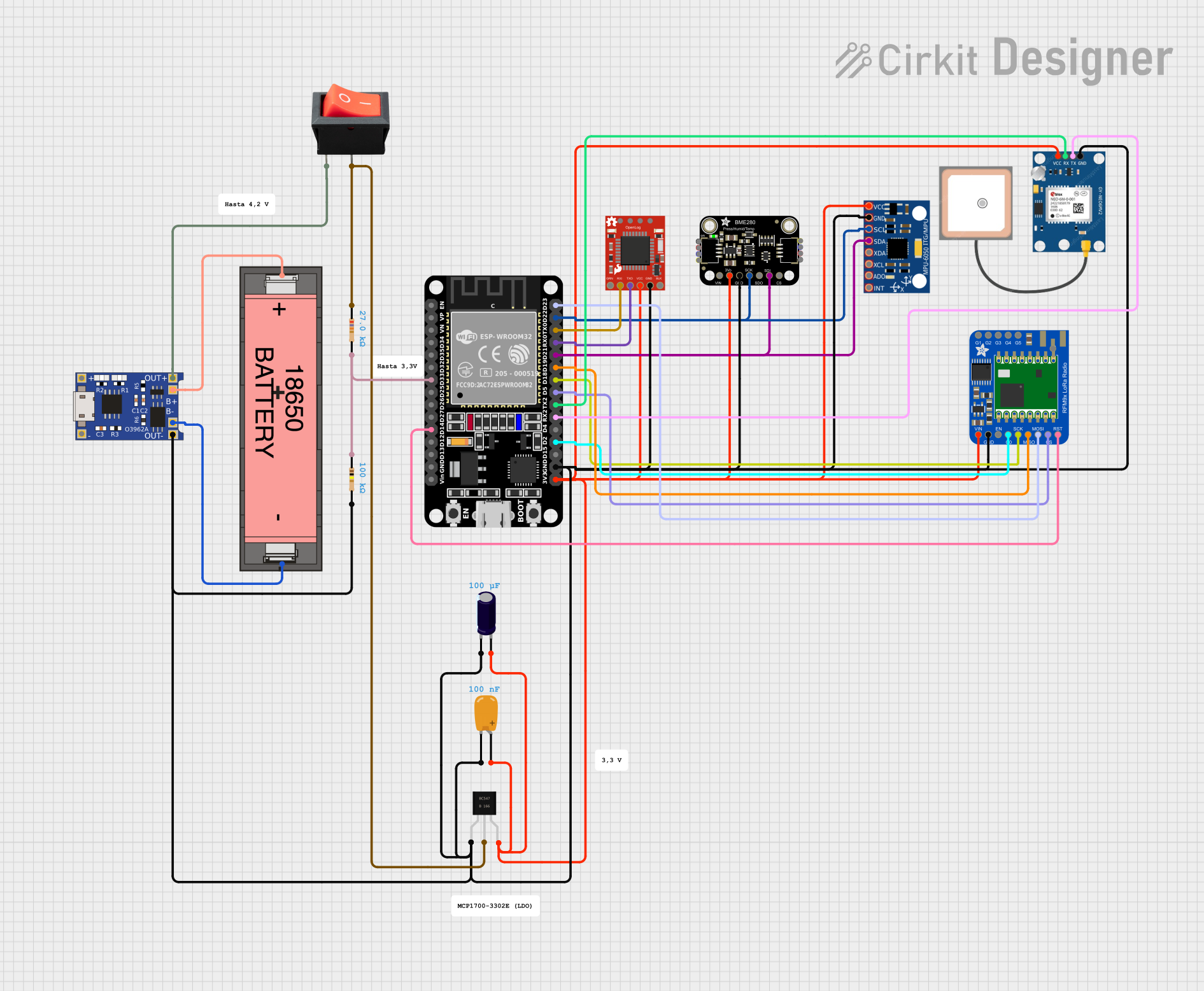


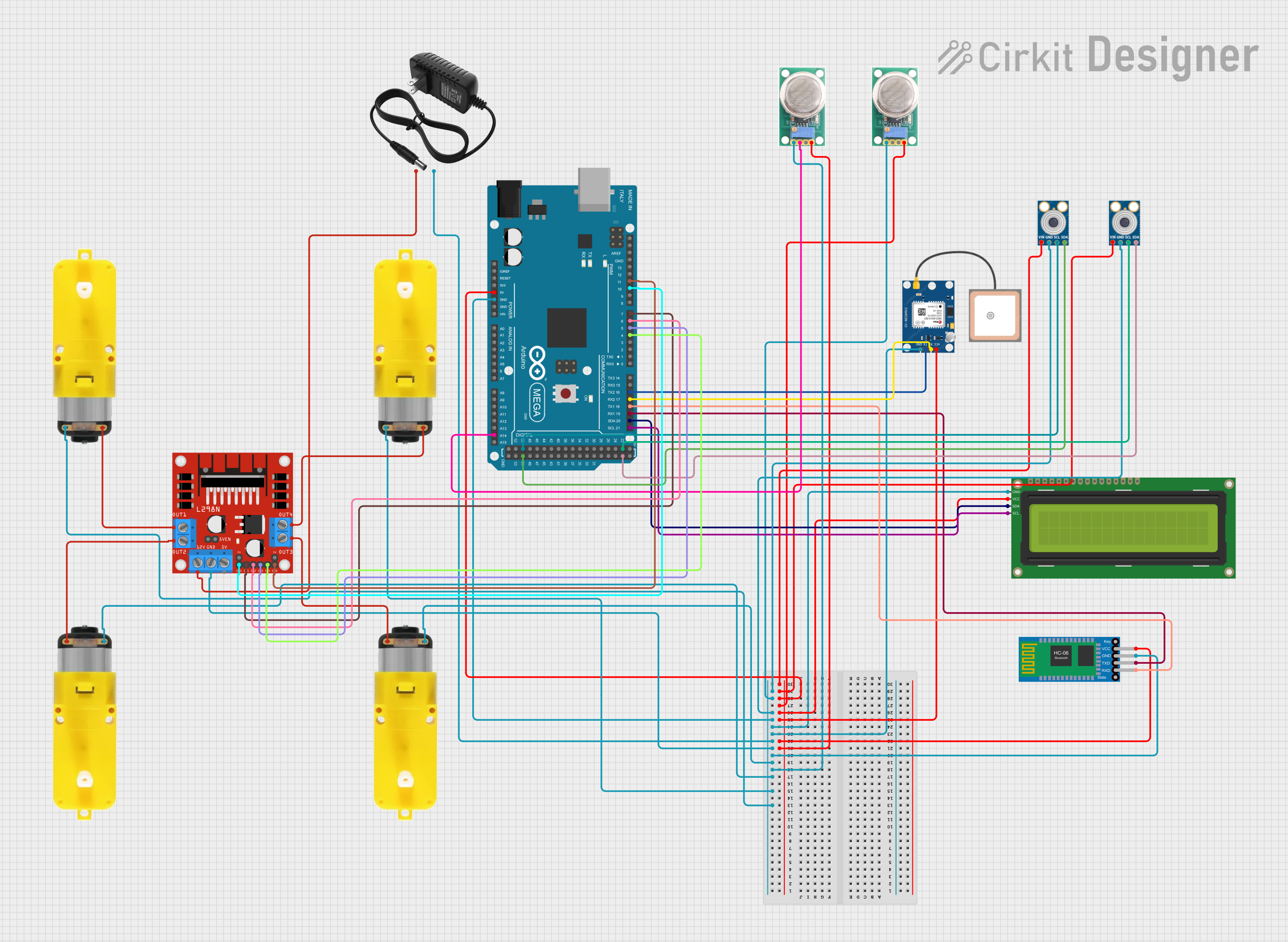
Explore Projects Built with Chopper Logics Board
Common Applications
- DC motor speed control in industrial and automotive systems
- Power supply regulation in renewable energy systems (e.g., solar inverters)
- Voltage conversion in battery-powered devices
- High-efficiency DC-DC converters for electronic systems
Technical Specifications
Key Technical Details
| Parameter | Value |
|---|---|
| Input Voltage Range | 5V to 48V DC |
| Output Voltage Range | Adjustable (based on chopper design) |
| Maximum Current Rating | 10A |
| Control Signal Voltage | 3.3V or 5V logic levels |
| Operating Temperature | -20°C to 85°C |
| Dimensions | 80mm x 50mm x 15mm |
| PCB Material | FR4, 2-layer |
| Manufacturer | Printed-Droids.net |
Pin Configuration and Descriptions
The Chopper Logics Board features a set of input/output pins for easy integration into your circuit. Below is the pin configuration:
| Pin Number | Pin Name | Description |
|---|---|---|
| 1 | VIN | Input voltage (5V to 48V DC) |
| 2 | GND | Ground connection |
| 3 | VOUT | Output voltage (adjustable based on chopper circuit design) |
| 4 | PWM_IN | PWM control signal input (3.3V or 5V logic levels) |
| 5 | ENABLE | Enable pin (active HIGH, 3.3V or 5V logic levels) |
| 6 | FAULT | Fault status output (active LOW, indicates an error condition) |
| 7 | TEMP_SENSE | Temperature sensor output (analog voltage proportional to board temperature) |
| 8 | SYNC | Synchronization input for multi-board operation |
Usage Instructions
How to Use the Chopper Logics Board in a Circuit
- Power Supply Connection: Connect the input voltage (VIN) and ground (GND) pins to a DC power source within the specified voltage range (5V to 48V DC).
- Output Connection: Connect the VOUT pin to the load or circuit requiring the regulated output voltage.
- Control Signal: Provide a PWM signal to the PWM_IN pin to control the chopper circuit's operation. Ensure the signal is within the supported logic levels (3.3V or 5V).
- Enable the Board: Set the ENABLE pin HIGH to activate the board. When the ENABLE pin is LOW, the board will remain in standby mode.
- Monitor Faults: Use the FAULT pin to monitor the board's status. If the pin is LOW, an error condition (e.g., overcurrent or overtemperature) has occurred.
- Temperature Monitoring: Optionally, connect the TEMP_SENSE pin to an analog input on a microcontroller to monitor the board's temperature.
- Synchronization: For multi-board setups, connect the SYNC pin to synchronize the operation of multiple Chopper Logics Boards.
Important Considerations and Best Practices
- Input Voltage: Ensure the input voltage is within the specified range to avoid damage to the board.
- Heat Dissipation: Use appropriate heat sinks or cooling mechanisms if operating at high currents or in high-temperature environments.
- PWM Signal: Use a stable and noise-free PWM signal to ensure smooth operation of the chopper circuit.
- Fault Handling: Implement fault-handling logic in your system to respond to error conditions indicated by the FAULT pin.
- Arduino Integration: The board can be easily interfaced with an Arduino UNO or similar microcontroller for control and monitoring.
Example Arduino Code
Below is an example of how to control the Chopper Logics Board using an Arduino UNO:
// Define pin connections
const int pwmPin = 9;       // PWM signal output pin
const int enablePin = 8;    // Enable pin
const int faultPin = 7;     // Fault status pin (input)
const int tempSensePin = A0; // Temperature sensor pin (analog input)

void setup() {
  pinMode(pwmPin, OUTPUT);       // Set PWM pin as output
  pinMode(enablePin, OUTPUT);    // Set Enable pin as output
  pinMode(faultPin, INPUT);      // Set Fault pin as input
  pinMode(tempSensePin, INPUT);  // Set Temp Sense pin as input

  digitalWrite(enablePin, HIGH); // Enable the Chopper Logics Board
}

void loop() {
  // Generate a PWM signal (50% duty cycle)
  analogWrite(pwmPin, 128); // 128/255 = 50% duty cycle

  // Check for fault condition
  if (digitalRead(faultPin) == LOW) {
    Serial.println("Fault detected! Check the board.");
    digitalWrite(enablePin, LOW); // Disable the board in case of fault
    while (1); // Halt execution
  }

  // Read and display temperature
  int tempValue = analogRead(tempSensePin);
  float voltage = tempValue * (5.0 / 1023.0); // Convert ADC value to voltage
  Serial.print("Board Temperature Voltage: ");
  Serial.println(voltage);

  delay(1000); // Wait for 1 second
}
Notes:
- Ensure the Arduino is powered by a suitable source when interfacing with the Chopper Logics Board.
- Adjust the PWM duty cycle in the code to control the output voltage of the chopper circuit.
Troubleshooting and FAQs
Common Issues and Solutions
| Issue | Possible Cause | Solution |
|---|---|---|
| Board does not power on | Incorrect input voltage or loose connection | Verify the input voltage and ensure secure connections to VIN and GND. |
| No output voltage | ENABLE pin is LOW | Set the ENABLE pin HIGH to activate the board. |
| Fault pin is LOW | Overcurrent or overtemperature condition | Check the load and ensure it is within the board's specifications. |
| Unstable output voltage | Noisy PWM signal | Use a stable PWM signal and ensure proper grounding. |
| High temperature during operation | Insufficient cooling | Add a heat sink or improve airflow around the board. |
FAQs
Can I use the Chopper Logics Board with a 12V battery?
- Yes, the board supports input voltages from 5V to 48V DC, so a 12V battery is compatible.
What happens if the FAULT pin goes LOW?
- A LOW signal on the FAULT pin indicates an error condition, such as overcurrent or overtemperature. Take appropriate action, such as reducing the load or improving cooling.
Can I synchronize multiple boards?
- Yes, use the SYNC pin to synchronize the operation of multiple Chopper Logics Boards.
Is the board compatible with 3.3V microcontrollers?
- Yes, the board supports both 3.3V and 5V logic levels for control signals.
By following this documentation, you can effectively integrate and operate the Chopper Logics Board in your electronic projects.