How to Use ESP32 GPIO Extension Board: Examples, Pinouts, and Specs
Introduction
The ESP32 GPIO Extension Board by Freenove is a versatile add-on designed to expand the General Purpose Input/Output (GPIO) capabilities of the ESP32 microcontroller. This board simplifies the process of connecting sensors, modules, and other electronic components to the ESP32, making it an essential tool for prototyping and development.
With its user-friendly design, the GPIO extension board provides easy access to the ESP32's pins, reducing the complexity of wiring and minimizing the risk of incorrect connections. It is ideal for hobbyists, students, and professionals working on IoT, robotics, and embedded systems projects.
Explore Projects Built with ESP32 GPIO Extension Board

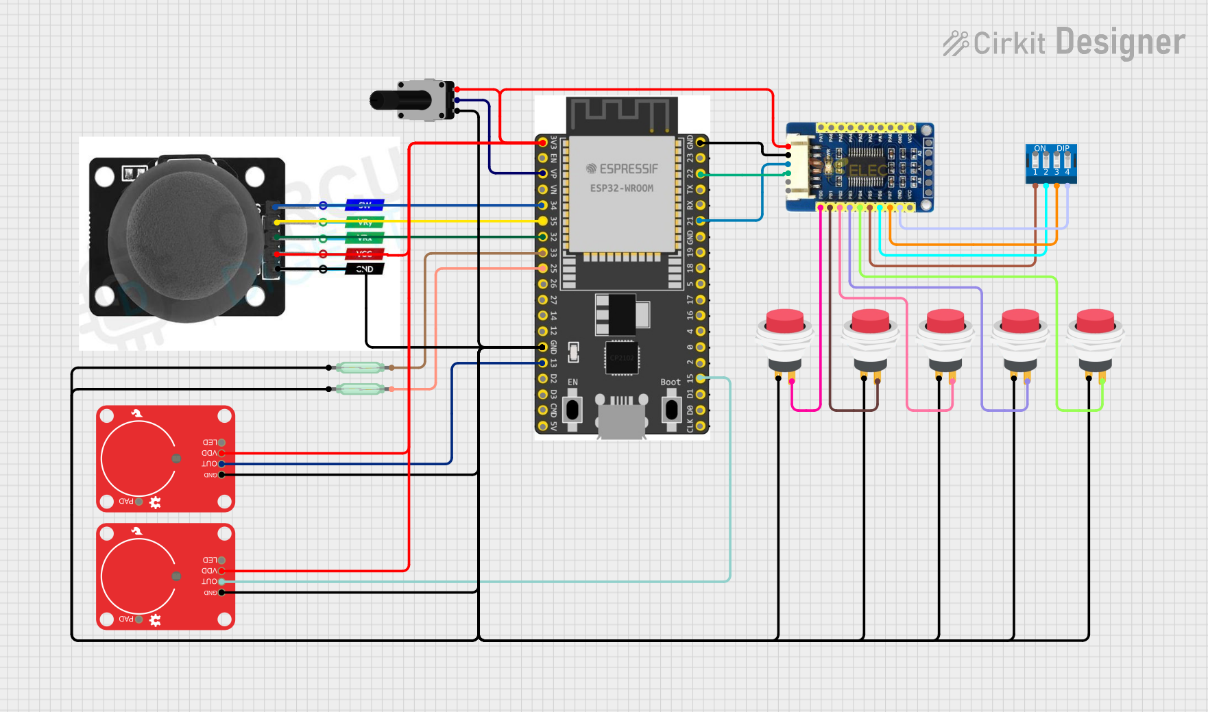
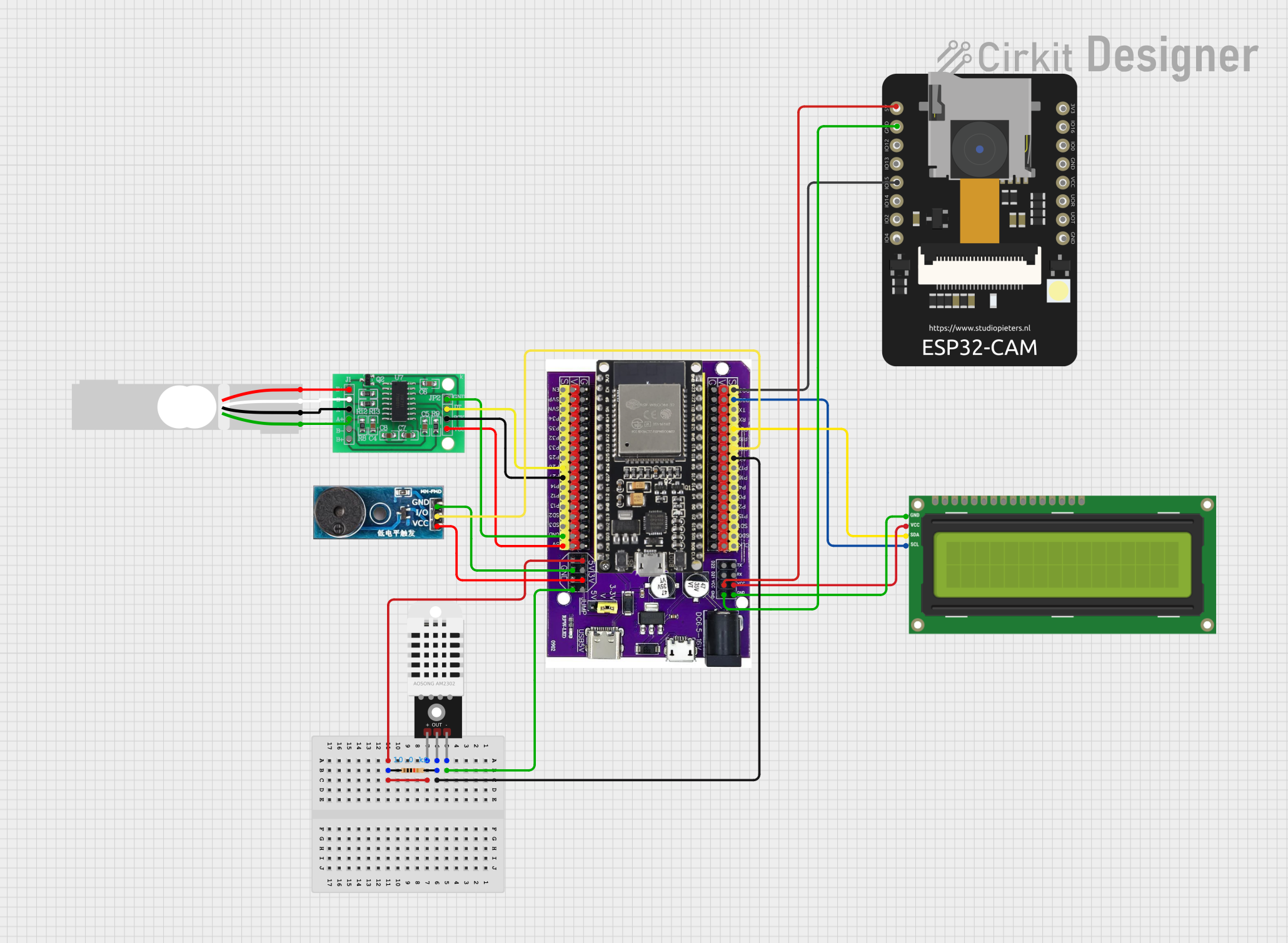
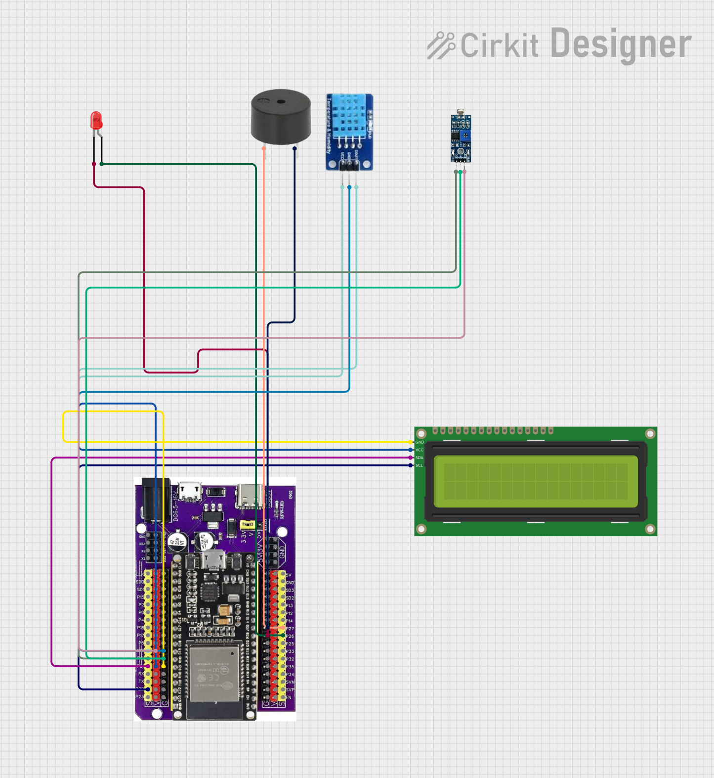
Explore Projects Built with ESP32 GPIO Extension Board
Common Applications and Use Cases
- Prototyping IoT devices and smart home systems
- Connecting multiple sensors and actuators to the ESP32
- Simplifying wiring in robotics projects
- Educational purposes for learning microcontroller programming
- Rapid development of embedded systems
Technical Specifications
Key Technical Details
- Compatible Microcontroller: ESP32
- Input Voltage: 3.3V (from ESP32 board)
- Output Voltage: 3.3V (regulated from ESP32)
- Pin Headers: Duplicates all GPIO pins of the ESP32
- Additional Features:
- Power and ground rails for easy connections
- Clear labeling for all pins
- Compact and lightweight design
- Dimensions: 60mm x 40mm x 10mm (approx.)
- Weight: ~15g
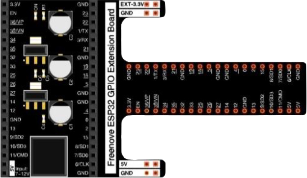
Pin Configuration and Descriptions
The GPIO extension board mirrors the ESP32's pinout, providing easy access to all GPIO pins. Below is a table summarizing the pin configuration:
| Pin Name | Description | Notes |
|---|---|---|
| GND | Ground | Common ground for all connections |
| 3.3V | 3.3V Power Output | Power supply for external components |
| GPIO0-GPIO39 | General Purpose I/O Pins | Digital/Analog input/output |
| VIN | Input Voltage (5V from USB) | Used to power the ESP32 via USB |
| EN | Enable Pin | Used to reset or enable the ESP32 |
| TX/RX | UART Communication Pins | For serial communication |
| SDA | I2C Data Line | For I2C communication |
| SCL | I2C Clock Line | For I2C communication |
| SPI Pins | SPI Communication (MOSI, MISO, SCK, CS) | For SPI-based devices |
Usage Instructions
How to Use the Component in a Circuit
Connect the ESP32 to the GPIO Extension Board:
- Align the ESP32's pins with the corresponding headers on the extension board.
- Ensure the ESP32 is securely seated to avoid loose connections.
Connect External Components:
- Use the labeled pin headers to connect sensors, actuators, or other modules.
- For power, use the 3.3V and GND rails provided on the board.
Power the System:
- Power the ESP32 via USB or an external power source. The GPIO extension board will draw power directly from the ESP32.
Program the ESP32:
- Write and upload your code to the ESP32 using the Arduino IDE or another compatible platform.
Important Considerations and Best Practices
- Voltage Levels: Ensure all connected components operate at 3.3V logic levels to avoid damaging the ESP32.
- Pin Current Limits: Do not exceed the maximum current rating of the ESP32 GPIO pins (typically 12mA per pin).
- Avoid Short Circuits: Double-check all connections to prevent accidental shorts.
- Use Pull-Up/Pull-Down Resistors: For stable input signals, use appropriate pull-up or pull-down resistors where necessary.
- I2C and SPI Devices: When using multiple I2C or SPI devices, ensure proper addressing and chip select configurations.
Example Code for Arduino UNO-Compatible Setup
Below is an example of how to use the GPIO extension board with an ESP32 to read a button press and control an LED:
// Define pin numbers for the button and LED
const int buttonPin = 4;  // GPIO4 connected to the button
const int ledPin = 2;     // GPIO2 connected to the LED

void setup() {
  // Initialize the button pin as an input
  pinMode(buttonPin, INPUT_PULLUP);

  // Initialize the LED pin as an output
  pinMode(ledPin, OUTPUT);

  // Start the serial monitor for debugging
  Serial.begin(115200);
  Serial.println("ESP32 GPIO Extension Board Example");
}

void loop() {
  // Read the state of the button
  int buttonState = digitalRead(buttonPin);

  // If the button is pressed, turn on the LED
  if (buttonState == LOW) { // Button pressed (active low)
    digitalWrite(ledPin, HIGH); // Turn on LED
    Serial.println("Button Pressed: LED ON");
  } else {
    digitalWrite(ledPin, LOW);  // Turn off LED
    Serial.println("Button Released: LED OFF");
  }

  // Add a small delay to debounce the button
  delay(50);
}
Troubleshooting and FAQs
Common Issues Users Might Face
ESP32 Not Powering On:
- Ensure the ESP32 is properly seated on the GPIO extension board.
- Check the USB cable and power source.
Incorrect Pin Connections:
- Double-check the pin labels on the extension board.
- Verify that the connected components are compatible with 3.3V logic.
Unresponsive Sensors or Modules:
- Confirm that the sensors/modules are receiving power.
- Check the wiring and ensure proper communication protocols (I2C, SPI, etc.) are used.
Overheating or Damage:
- Avoid drawing excessive current from the GPIO pins.
- Use external power sources for high-power components.
Solutions and Tips for Troubleshooting
- Use a multimeter to verify voltage levels and continuity.
- Test individual components separately before integrating them into the circuit.
- Refer to the ESP32 datasheet for detailed pin specifications and limitations.
- If using I2C devices, scan for connected devices using an I2C scanner sketch to verify addresses.
By following this documentation, you can effectively utilize the Freenove ESP32 GPIO Extension Board for your projects, ensuring reliable and efficient operation.