How to Use Adafruit PyBadge: Examples, Pinouts, and Specs
Introduction
The Adafruit PyBadge is an all-in-one compact electronic badge designed for creating portable gaming projects, wearable electronics, and educational programming. It is based on the powerful ATSAMD51 microcontroller and comes equipped with a 1.8" color TFT display, making it ideal for displaying game graphics, text, and images. The PyBadge is also outfitted with a speaker for audio output, an accelerometer for motion sensing, and multiple buttons for user interaction. Pre-loaded with CircuitPython firmware, the PyBadge is easily programmable via the Arduino IDE or CircuitPython, offering a versatile platform for users ranging from beginners to advanced electronics enthusiasts.
Common applications of the Adafruit PyBadge include:
- DIY gaming consoles
- Interactive name badges for events
- Educational tools for teaching programming and electronics
- Wearable electronic projects
- Prototyping user interfaces
Explore Projects Built with Adafruit PyBadge


Explore Projects Built with Adafruit PyBadge
Technical Specifications
Key Technical Details
- Microcontroller: ATSAMD51J19
- Operating Voltage: 3.3V
- Input Voltage (recommended): 5V via USB or battery
- Display: 1.8" 160x128 Color TFT
- Sound: Mono audio output with a Class-D amplifier
- Sensors: LIS3DH triple-axis accelerometer
- User Inputs: 8 x game/control buttons, 1 x reset button
- Connectivity: USB, JST-PH battery connector
- Programming: Pre-loaded with CircuitPython, compatible with Arduino IDE
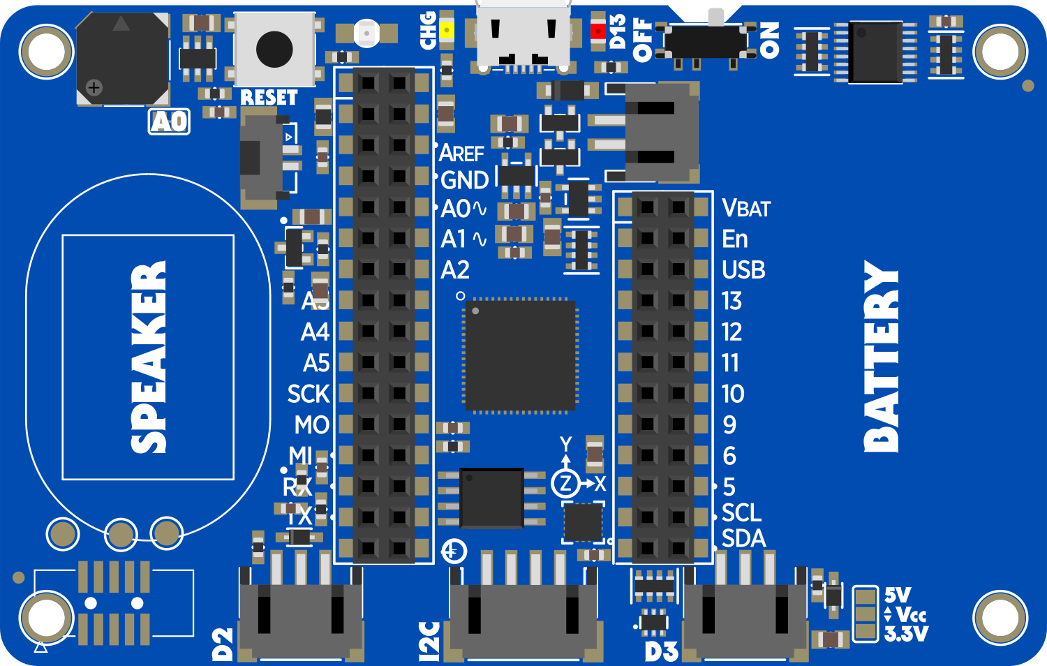
Pin Configuration and Descriptions
| Pin Number | Name | Description |
|---|---|---|
| 1 | VOUT | 3.3V output from the regulator |
| 2 | GND | Ground |
| 3 | BAT | Battery input for an optional LiPo battery |
| 4 | EN | Enable pin for the 3.3V regulator |
| 5 | USB | USB data pin for programming and serial monitor |
| 6 | SDA | I2C data line |
| 7 | SCL | I2C clock line |
| 8 | A1 | Analog input or GPIO pin |
| 9 | A2 | Analog input or GPIO pin |
| 10 | A3 | Analog input or GPIO pin |
| 11 | A4 | Analog input or GPIO pin |
| 12 | A5 | Analog input or GPIO pin |
| 13 | A6 | Analog input or GPIO pin |
| 14 | A7 | Analog input or GPIO pin |
| 15 | TX | UART transmit pin |
| 16 | RX | UART receive pin |
Usage Instructions
Circuit Integration
To use the Adafruit PyBadge in a circuit:
- Powering the PyBadge: Connect the PyBadge to a power source via the USB port or attach a LiPo battery to the JST-PH connector.
- Programming: Connect the PyBadge to a computer using a USB cable. The device should be recognized as a USB drive if using CircuitPython or as a port in the Arduino IDE.
- Display and Audio: Utilize the built-in display and speaker for visual and audio output in your projects.
- Sensors and Inputs: Take advantage of the accelerometer and buttons for interactive projects.
Best Practices
- Always disconnect the PyBadge from the power source before making or altering connections.
- When using a LiPo battery, ensure it is properly charged and connected with the correct polarity.
- Use anti-static measures when handling the PyBadge to prevent electrostatic discharge damage.
Troubleshooting and FAQs
Common Issues
- PyBadge not recognized by computer: Ensure the USB cable is properly connected and functioning. Try a different USB port or cable if necessary.
- Display not working: Check that the PyBadge is adequately powered and that the firmware is correctly loaded.
- Buttons not responding: Verify that the code is correctly implemented for button inputs and that there are no obstructions or dirt under the buttons.
Solutions and Tips
- Resetting the PyBadge: If the device is unresponsive, use the reset button to reboot the PyBadge.
- Updating Firmware: To ensure compatibility and stability, keep the PyBadge firmware up to date with the latest version from Adafruit.
FAQs
Q: Can I program the PyBadge with Arduino IDE? A: Yes, the PyBadge is compatible with the Arduino IDE. Make sure to install the necessary board definitions and libraries.
Q: What is CircuitPython? A: CircuitPython is a version of Python designed to run on microcontrollers, making it easy to write simple and readable code for hardware projects.
Q: How do I load new games or programs onto the PyBadge?
A: With CircuitPython, you can simply drag and drop your .py files onto the PyBadge USB drive. For Arduino, upload your sketch via the Arduino IDE.
Example Code for Arduino UNO
Below is a simple example of how to initialize the display and draw some text using the Arduino IDE:
#include <Adafruit_GFX.h>    // Core graphics library
#include <Adafruit_ST7735.h> // Hardware-specific library for ST7735
#include <SPI.h>

// Pin definitions for the PyBadge
#define TFT_CS        10
#define TFT_RST       12
#define TFT_DC        9

// Create the display object
Adafruit_ST7735 tft = Adafruit_ST7735(TFT_CS, TFT_DC, TFT_RST);

void setup() {
  tft.initR(INITR_144GREENTAB); // Initialize the display
  tft.fillScreen(ST7735_BLACK);  // Clear the screen to black
  tft.setCursor(0, 0);           // Set the cursor to the top-left corner
  tft.setTextColor(ST7735_WHITE); // Set the text color to white
  tft.setTextWrap(true);          // Allow text to wrap to the next line
  tft.print("Hello, PyBadge!");   // Print a message to the display
}

void loop() {
  // No need to repeat the text display
}
Remember to install the Adafruit GFX and ST7735 libraries before compiling this code. This example initializes the display and prints "Hello, PyBadge!" on the screen.