How to Use Heltec Wireless Stick V3: Examples, Pinouts, and Specs
Introduction
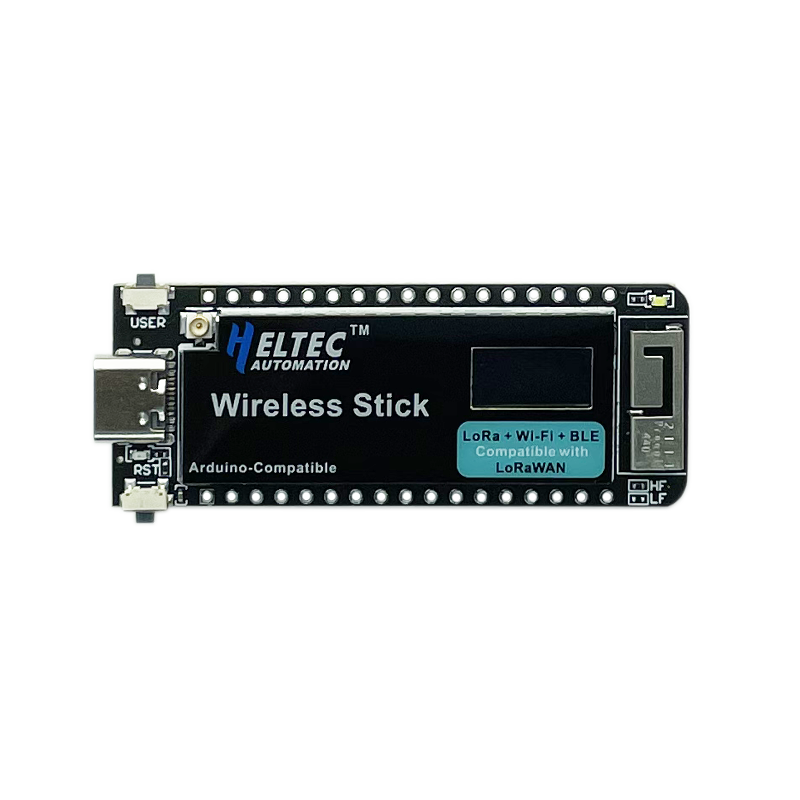
The Heltec Wireless Stick V3 is a compact and versatile development board designed by Heltec Automation. It features the powerful ESP32 chip, an integrated 0.96-inch OLED display, and built-in LoRa wireless communication capabilities. This board is ideal for IoT (Internet of Things) projects, prototyping, and applications requiring low-power, long-range wireless communication.
Explore Projects Built with Heltec Wireless Stick V3


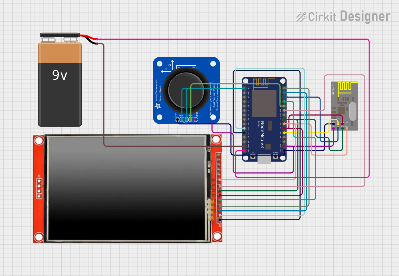
Explore Projects Built with Heltec Wireless Stick V3
Common Applications and Use Cases
- IoT devices and smart home systems
- Environmental monitoring and data logging
- Remote sensing and telemetry
- Wireless communication in industrial automation
- Prototyping for LoRaWAN networks
Technical Specifications
The following table outlines the key technical specifications of the Heltec Wireless Stick V3:
| Parameter | Specification |
|---|---|
| Microcontroller | ESP32 (dual-core, 32-bit, Xtensa LX6 processor) |
| Clock Speed | Up to 240 MHz |
| Flash Memory | 8 MB |
| SRAM | 520 KB |
| Wireless Connectivity | Wi-Fi (802.11 b/g/n), Bluetooth 4.2, LoRa (SX1262) |
| LoRa Frequency Bands | 433 MHz, 868 MHz, 915 MHz (region-specific) |
| OLED Display | 0.96-inch, 128x64 resolution, monochrome |
| Operating Voltage | 3.3V |
| Input Voltage Range | 5V (via USB-C) |
| GPIO Pins | 21 (including ADC, DAC, I2C, SPI, UART, PWM) |
| Power Consumption | ~10 µA in deep sleep mode |
| Dimensions | 75 mm x 25 mm x 8 mm |
Pin Configuration and Descriptions
The Heltec Wireless Stick V3 features a variety of pins for interfacing with external components. Below is the pinout description:
| Pin Name | Type | Description |
|---|---|---|
| GND | Power | Ground connection |
| 3V3 | Power | 3.3V power output |
| VIN | Power | Input voltage (5V via USB-C) |
| GPIO0 | Digital I/O | General-purpose I/O, also used for boot mode selection |
| GPIO1 | Digital I/O | General-purpose I/O, UART TX |
| GPIO2 | Digital I/O | General-purpose I/O, UART RX |
| GPIO21 | I2C SDA | I2C data line |
| GPIO22 | I2C SCL | I2C clock line |
| GPIO25 | DAC1 | Digital-to-Analog Converter output 1 |
| GPIO26 | DAC2 | Digital-to-Analog Converter output 2 |
| GPIO34 | ADC1 | Analog-to-Digital Converter input |
| RST | Reset | Reset pin |
Usage Instructions
How to Use the Heltec Wireless Stick V3 in a Circuit
Powering the Board:
- Connect the board to a 5V power source using the USB-C port.
- Alternatively, supply 3.3V directly to the 3V3 pin.
Programming the Board:
- Install the Arduino IDE and add the ESP32 board support package.
- Select "Heltec Wireless Stick V3" from the board manager.
- Connect the board to your computer via USB-C and upload your code.
Using the OLED Display:
- The OLED display is connected via I2C (SDA: GPIO21, SCL: GPIO22).
- Use the Heltec ESP32 library to control the display.
LoRa Communication:
- Install the LoRa library in the Arduino IDE.
- Configure the frequency band according to your region (e.g., 868 MHz for Europe).
- Use the LoRa pins (internally connected) for wireless communication.
Important Considerations and Best Practices
- Ensure the correct LoRa frequency band is selected to comply with local regulations.
- Avoid powering the board with voltages higher than 5V to prevent damage.
- Use proper pull-up resistors for I2C communication if external devices are connected.
- For low-power applications, utilize the deep sleep mode to minimize power consumption.
- Always handle the board in an ESD-safe environment to prevent static damage.
Example Code for Arduino UNO
Below is an example code snippet to display text on the OLED and send a LoRa message:
#include <Wire.h>
#include <Heltec.h> // Include the Heltec ESP32 library

void setup() {
  // Initialize the Heltec board
  Heltec.begin(true /*DisplayEnable*/, true /*LoRaEnable*/, true /*SerialEnable*/);

  // Display a message on the OLED
  Heltec.display->clear();
  Heltec.display->drawString(0, 0, "Hello, Heltec!");
  Heltec.display->display();

  // Initialize LoRa communication
  if (!LoRa.begin(868E6)) { // Set frequency to 868 MHz
    Serial.println("LoRa initialization failed!");
    while (1);
  }
  Serial.println("LoRa initialized successfully.");
}

void loop() {
  // Send a LoRa message
  LoRa.beginPacket();
  LoRa.print("Hello, LoRa!");
  LoRa.endPacket();

  // Wait for 5 seconds before sending the next message
  delay(5000);
}
Troubleshooting and FAQs
Common Issues and Solutions
The board is not detected by the computer:
- Ensure the USB-C cable is a data cable (not just a charging cable).
- Check if the correct drivers for the ESP32 are installed.
LoRa communication is not working:
- Verify that both sender and receiver are configured to the same frequency.
- Ensure the antennas are properly connected to the boards.
OLED display is not showing anything:
- Confirm that the Heltec library is installed and initialized correctly.
- Check the I2C connections (SDA and SCL pins).
High power consumption in sleep mode:
- Ensure all peripherals are disabled before entering deep sleep.
- Use the
esp_deep_sleep_start()function to minimize power usage.
FAQs
Can I use the Heltec Wireless Stick V3 with other IDEs?
Yes, the board is compatible with the PlatformIO IDE and ESP-IDF framework.What is the maximum range of LoRa communication?
The range depends on environmental factors but can reach up to 10 km in open areas.Does the board support battery power?
Yes, the board has a JST connector for a LiPo battery and includes a charging circuit.Can I use the board without the OLED display?
Yes, you can disable the OLED in the code by settingDisplayEnabletofalseinHeltec.begin().
This concludes the documentation for the Heltec Wireless Stick V3.