How to Use Solar Cell: Examples, Pinouts, and Specs
Introduction
A solar cell is a device that converts light energy directly into electrical energy through the photovoltaic effect. It is a fundamental building block of solar panels and is widely used to harness renewable energy from the sun. Solar cells are commonly found in applications such as residential and commercial solar power systems, portable solar chargers, solar-powered calculators, and off-grid energy solutions.
By utilizing sunlight as a clean and sustainable energy source, solar cells play a critical role in reducing reliance on fossil fuels and minimizing environmental impact.
Explore Projects Built with Solar Cell


Explore Projects Built with Solar Cell
Technical Specifications
Below are the general technical specifications of a typical silicon-based solar cell. Note that actual values may vary depending on the specific model and manufacturer.
Key Specifications
- Material: Monocrystalline or polycrystalline silicon (common types)
- Open-Circuit Voltage (Voc): 0.5V to 0.7V per cell
- Short-Circuit Current (Isc): Typically 2A to 9A (depending on size and sunlight intensity)
- Maximum Power Output (Pmax): Varies by size, typically 1W to 300W for individual cells or modules
- Efficiency: 15% to 22% (for commercial-grade cells)
- Operating Temperature Range: -40°C to +85°C
- Standard Test Conditions (STC): 1000 W/m² irradiance, 25°C cell temperature, AM1.5 spectrum
Pin Configuration and Descriptions
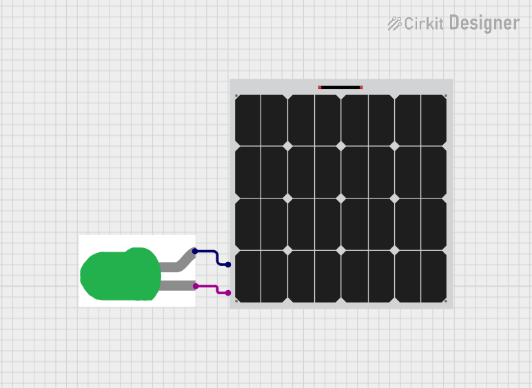
Solar cells typically have two terminals: a positive terminal and a negative terminal. These terminals are used to connect the solar cell to a load or a circuit.
| Pin | Description |
|---|---|
| Positive (+) | The anode terminal where current flows out of the solar cell. |
| Negative (-) | The cathode terminal where current flows into the solar cell. |
Usage Instructions
How to Use a Solar Cell in a Circuit
- Determine the Load Requirements: Calculate the voltage and current requirements of the load you want to power.
- Connect Multiple Cells (if needed):
- For higher voltage: Connect solar cells in series (positive to negative).
- For higher current: Connect solar cells in parallel (positive to positive, negative to negative).
- Use a Charge Controller: If charging a battery, use a charge controller to regulate the voltage and prevent overcharging.
- Add a Blocking Diode: Place a diode in series with the positive terminal to prevent reverse current flow at night or in low light.
- Test the Output: Use a multimeter to measure the voltage and current output under sunlight.
Important Considerations and Best Practices
- Sunlight Exposure: Ensure the solar cell is placed in direct sunlight for maximum efficiency.
- Angle and Orientation: Position the solar cell at an angle that maximizes sunlight exposure based on your geographic location.
- Temperature Effects: Be aware that high temperatures can reduce the efficiency of the solar cell.
- Avoid Shading: Even partial shading can significantly reduce the output of the solar cell.
- Use Proper Wiring: Use wires with appropriate current ratings to avoid overheating or power loss.
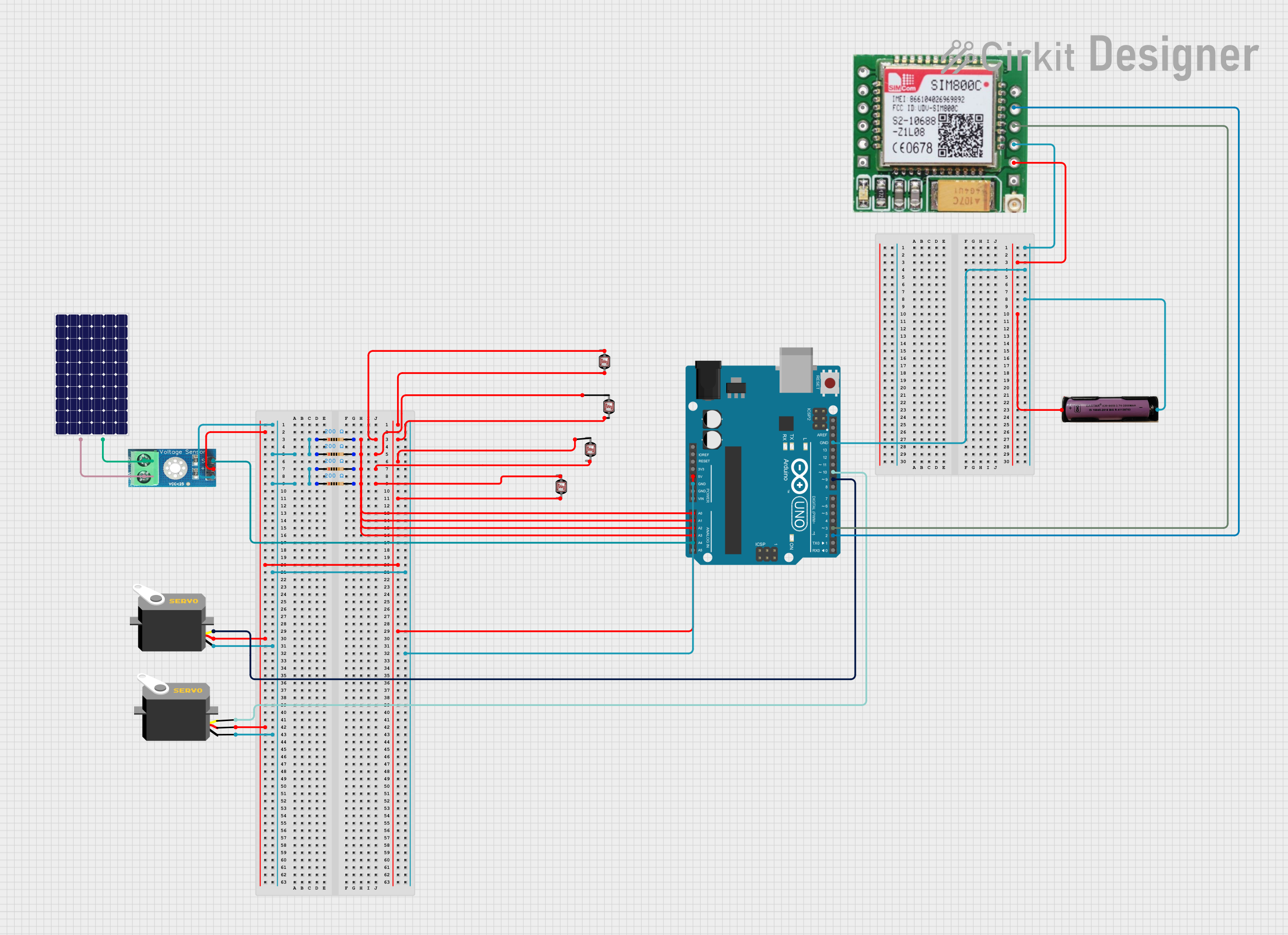
Example: Connecting a Solar Cell to an Arduino UNO
Below is an example of how to use a solar cell to power an Arduino UNO with a battery and charge controller.
Circuit Components
- 1 Solar Cell (6V, 1W)
- 1 Rechargeable Battery (e.g., 3.7V Li-ion)
- 1 Charge Controller Module
- Arduino UNO
- Connecting Wires
Code Example
// Example code to read voltage from a solar cell using Arduino UNO
// Ensure the solar cell is connected to a battery and charge controller
// before connecting to the Arduino for safe operation.

const int solarPin = A0; // Analog pin connected to the solar cell output
float voltage = 0.0;

void setup() {
  Serial.begin(9600); // Initialize serial communication
}

void loop() {
  int sensorValue = analogRead(solarPin); // Read the analog value
  voltage = sensorValue * (5.0 / 1023.0); // Convert to voltage (5V reference)

  // Print the voltage to the Serial Monitor
  Serial.print("Solar Cell Voltage: ");
  Serial.print(voltage);
  Serial.println(" V");

  delay(1000); // Wait for 1 second before the next reading
}
Troubleshooting and FAQs
Common Issues and Solutions
Low or No Output Voltage:
- Cause: Insufficient sunlight or shading.
- Solution: Ensure the solar cell is in direct sunlight and free from obstructions.
Overheating of Wires:
- Cause: Using wires with insufficient current rating.
- Solution: Use wires with appropriate thickness based on the current output of the solar cell.
Reverse Current Flow at Night:
- Cause: Absence of a blocking diode.
- Solution: Install a blocking diode in series with the positive terminal.
Reduced Efficiency:
- Cause: High temperatures or dirt on the solar cell surface.
- Solution: Clean the solar cell regularly and ensure proper ventilation to reduce heat buildup.
FAQs
Q: Can I connect a solar cell directly to a battery?
- A: It is not recommended. Use a charge controller to regulate the voltage and prevent overcharging.
Q: How do I calculate the power output of a solar cell?
- A: Multiply the voltage (V) by the current (I) to get the power (P = V × I).
Q: Can solar cells work indoors?
- A: Solar cells can work under artificial light, but the output will be significantly lower compared to direct sunlight.
Q: What happens if one solar cell in a series connection is shaded?
- A: The output of the entire series connection will drop significantly. Use bypass diodes to mitigate this issue.