How to Use Arduino Joystick Shield: Examples, Pinouts, and Specs
Introduction
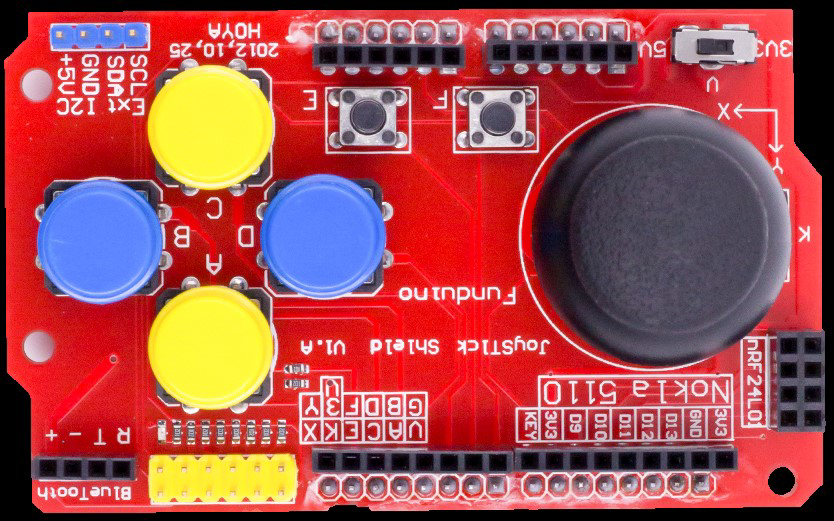
The Arduino Joystick Shield by Funduino is a versatile add-on for Arduino boards that provides joystick control capabilities. It features an analog joystick module and several additional buttons, making it ideal for projects requiring user input, such as gaming controllers, robotic control systems, and menu navigation interfaces. The shield is designed to fit directly onto an Arduino board, simplifying the integration process.
Explore Projects Built with Arduino Joystick Shield
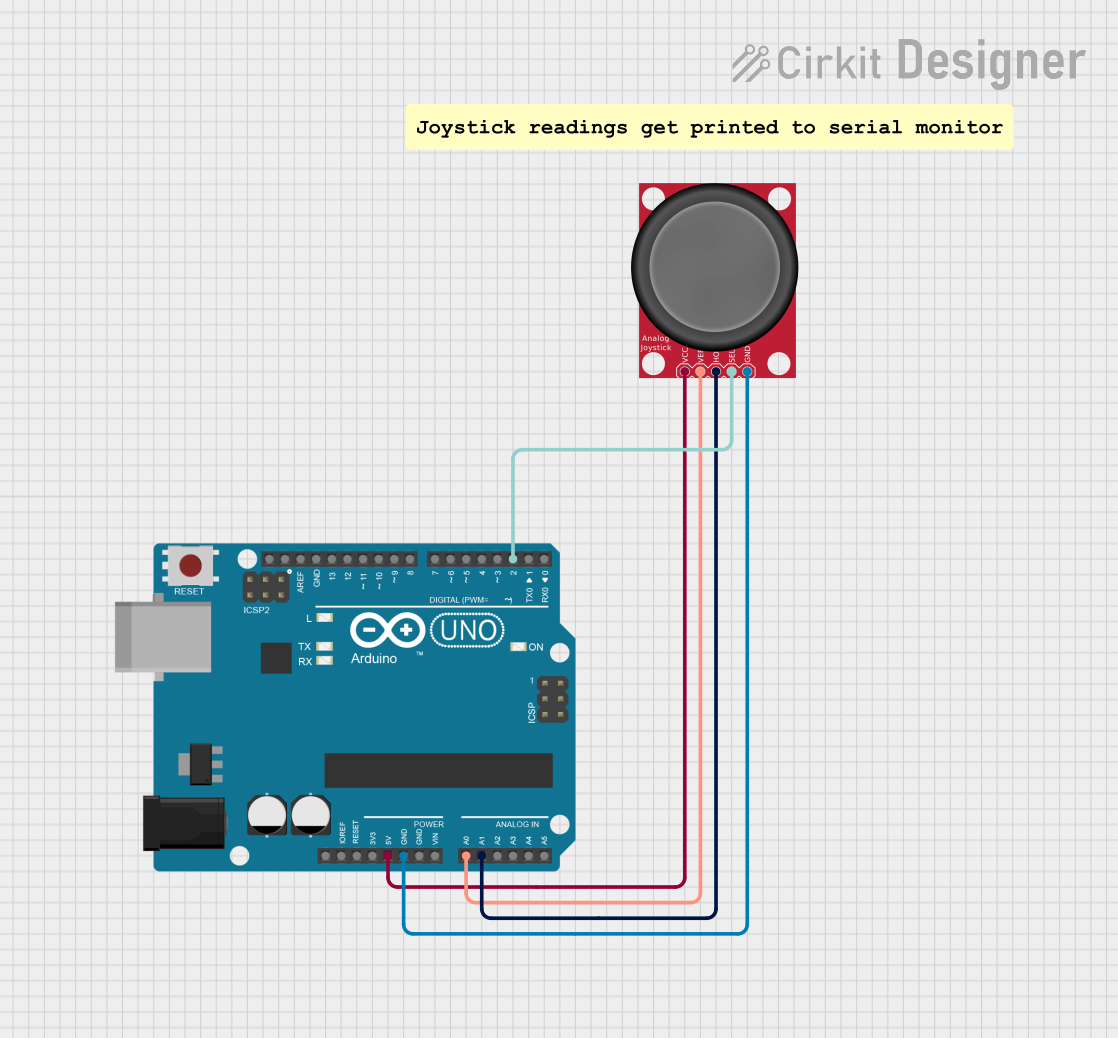
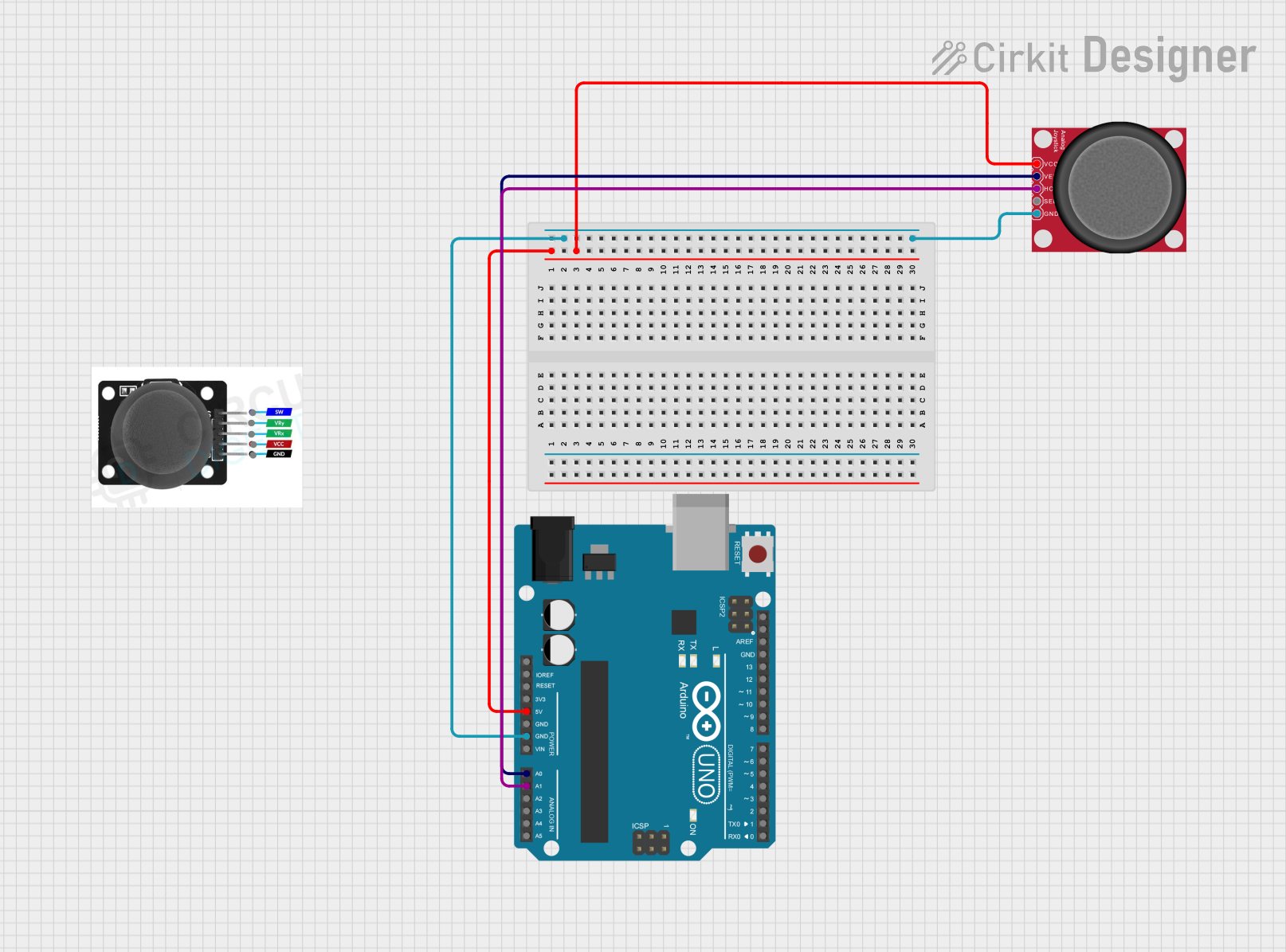

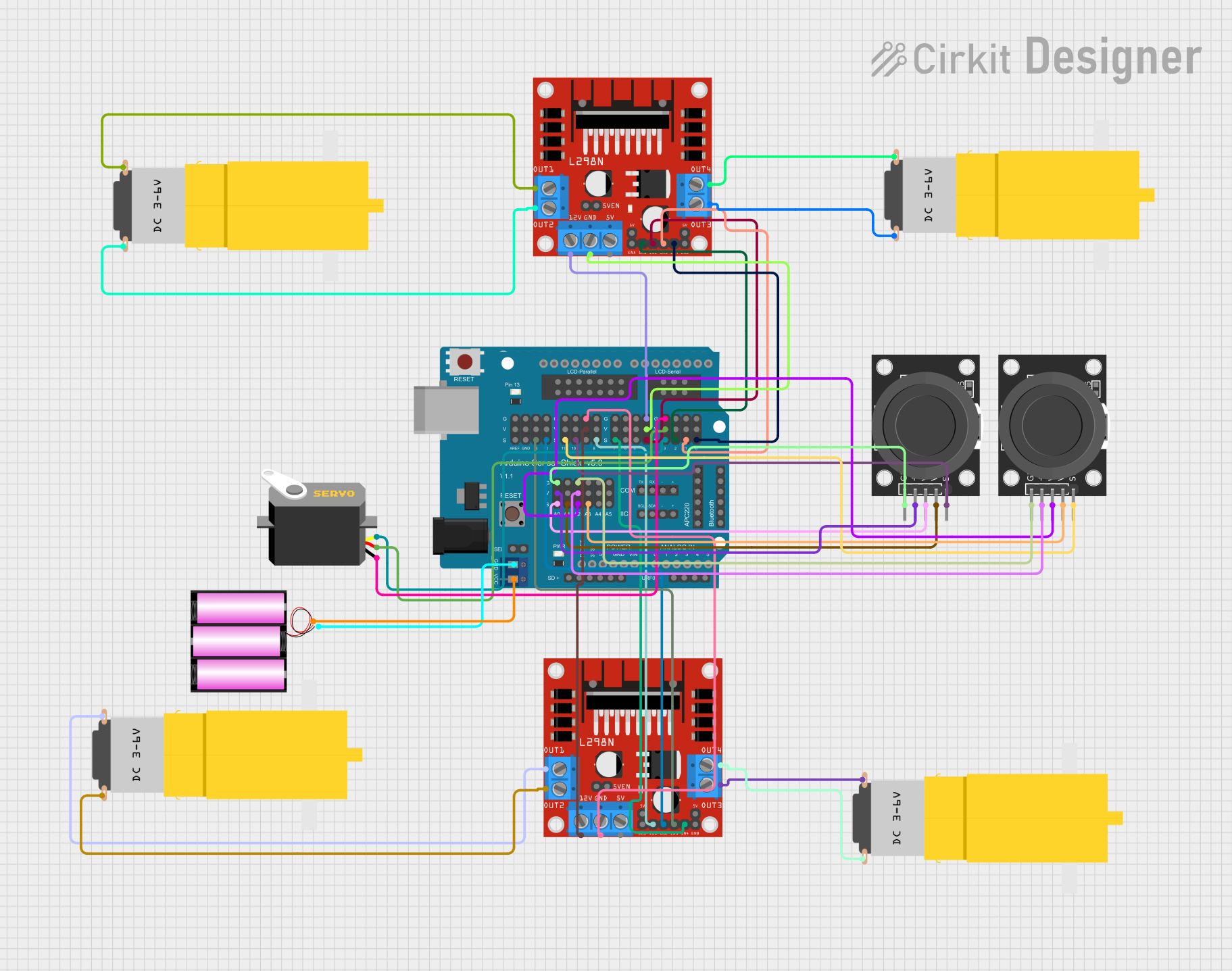
Explore Projects Built with Arduino Joystick Shield
Common Applications and Use Cases
- DIY gaming controllers
- Robotic control systems
- Remote-controlled vehicles
- Menu navigation for embedded systems
- Interactive art installations
Technical Specifications
The Arduino Joystick Shield is designed to work seamlessly with Arduino boards, offering a combination of analog and digital inputs for versatile control.
Key Technical Details
- Manufacturer Part ID: Joystick Shield
- Operating Voltage: 5V (powered by the Arduino board)
- Analog Inputs: 2 (X-axis and Y-axis of the joystick)
- Digital Inputs: 7 (5 buttons on the shield, plus joystick button and D-pad)
- Communication: Direct pin connections to the Arduino board
- Dimensions: Standard Arduino shield size
Pin Configuration and Descriptions
The shield connects to the Arduino board via its standard pin headers. Below is the pin configuration:
| Pin | Function | Description |
|---|---|---|
| A0 | Joystick X-axis | Reads the horizontal position of the joystick (analog input). |
| A1 | Joystick Y-axis | Reads the vertical position of the joystick (analog input). |
| D2 | Button 1 | Digital input for Button 1 (labeled on the shield). |
| D3 | Button 2 | Digital input for Button 2 (labeled on the shield). |
| D4 | Button 3 | Digital input for Button 3 (labeled on the shield). |
| D5 | Button 4 | Digital input for Button 4 (labeled on the shield). |
| D6 | Button 5 | Digital input for Button 5 (labeled on the shield). |
| D7 | Joystick Button (SW) | Digital input for the joystick's built-in button (activated by pressing down). |
| D8 | D-pad Up | Digital input for the D-pad's "Up" button. |
| D9 | D-pad Down | Digital input for the D-pad's "Down" button. |
| D10 | D-pad Left | Digital input for the D-pad's "Left" button. |
| D11 | D-pad Right | Digital input for the D-pad's "Right" button. |
Usage Instructions
The Arduino Joystick Shield is easy to use and integrates directly with an Arduino board. Follow the steps below to get started:
Step 1: Connecting the Shield
- Align the shield's pin headers with the corresponding pins on the Arduino board.
- Press the shield firmly onto the Arduino board to ensure a secure connection.
- Connect the Arduino board to your computer via USB for power and programming.
Step 2: Reading Inputs
The joystick and buttons can be read using the Arduino IDE. The joystick provides two analog inputs (X and Y axes) and one digital input (joystick button). The other buttons and D-pad provide digital inputs.
Example Code
Below is an example Arduino sketch to read the joystick and button inputs:
// Define pin assignments for the joystick and buttons
const int joystickX = A0; // Joystick X-axis (analog)
const int joystickY = A1; // Joystick Y-axis (analog)
const int joystickSW = 7; // Joystick button (digital)
const int button1 = 2;    // Button 1 (digital)
const int button2 = 3;    // Button 2 (digital)
const int button3 = 4;    // Button 3 (digital)
const int button4 = 5;    // Button 4 (digital)
const int button5 = 6;    // Button 5 (digital)

// Setup function to initialize pins
void setup() {
  Serial.begin(9600); // Start serial communication for debugging

  // Set button pins as inputs with pull-up resistors
  pinMode(joystickSW, INPUT_PULLUP);
  pinMode(button1, INPUT_PULLUP);
  pinMode(button2, INPUT_PULLUP);
  pinMode(button3, INPUT_PULLUP);
  pinMode(button4, INPUT_PULLUP);
  pinMode(button5, INPUT_PULLUP);
}

// Main loop to read and display inputs
void loop() {
  // Read joystick analog values
  int xValue = analogRead(joystickX);
  int yValue = analogRead(joystickY);

  // Read button states (LOW = pressed, HIGH = not pressed)
  bool joystickPressed = !digitalRead(joystickSW);
  bool button1Pressed = !digitalRead(button1);
  bool button2Pressed = !digitalRead(button2);
  bool button3Pressed = !digitalRead(button3);
  bool button4Pressed = !digitalRead(button4);
  bool button5Pressed = !digitalRead(button5);

  // Print joystick and button states to the Serial Monitor
  Serial.print("Joystick X: ");
  Serial.print(xValue);
  Serial.print(" | Joystick Y: ");
  Serial.print(yValue);
  Serial.print(" | Joystick Button: ");
  Serial.print(joystickPressed);
  Serial.print(" | Button 1: ");
  Serial.print(button1Pressed);
  Serial.print(" | Button 2: ");
  Serial.print(button2Pressed);
  Serial.print(" | Button 3: ");
  Serial.print(button3Pressed);
  Serial.print(" | Button 4: ");
  Serial.print(button4Pressed);
  Serial.print(" | Button 5: ");
  Serial.println(button5Pressed);

  delay(100); // Add a small delay for stability
}
Important Considerations and Best Practices
- Ensure the shield is securely connected to the Arduino board to avoid loose connections.
- Use pull-up resistors for digital inputs to ensure stable readings.
- Avoid applying excessive force to the joystick or buttons to prevent damage.
- Use the Serial Monitor in the Arduino IDE to debug and verify input readings.
Troubleshooting and FAQs
Common Issues and Solutions
Joystick or buttons not responding:
- Ensure the shield is properly seated on the Arduino board.
- Verify that the correct pins are defined in your code.
- Check for loose or damaged connections.
Incorrect or fluctuating analog readings:
- Ensure the joystick is in a neutral position when testing.
- Add a small delay in the code to stabilize readings.
Serial Monitor not displaying data:
- Confirm that the correct COM port is selected in the Arduino IDE.
- Ensure the baud rate in the Serial Monitor matches the
Serial.begin()value in the code.
FAQs
Q: Can I use this shield with boards other than Arduino UNO?
A: Yes, the shield is compatible with other Arduino boards that have the same pin layout, such as the Arduino Mega or Leonardo.
Q: How do I calibrate the joystick?
A: You can map the analog readings from the joystick to a specific range using the map() function in Arduino.
Q: Can I use this shield for wireless control?
A: Yes, you can pair the shield with a wireless module (e.g., NRF24L01 or Bluetooth) for remote control applications.
By following this documentation, you can effectively integrate and use the Arduino Joystick Shield in your projects!