How to Use ESP-01S Porgramer-Adapter: Examples, Pinouts, and Specs
Introduction
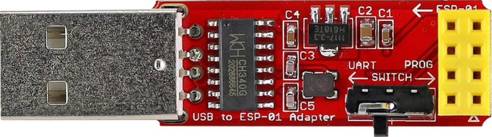
The ESP-01S Programmer-Adapter by Wishiot (Manufacturer Part ID: 747356634557) is a compact and efficient programming adapter designed specifically for the ESP-01S Wi-Fi module. This adapter simplifies the process of connecting the ESP-01S module to a computer for firmware uploading, debugging, and testing. It eliminates the need for complex wiring setups, making it an essential tool for developers working with ESP-01S modules.
Explore Projects Built with ESP-01S Porgramer-Adapter


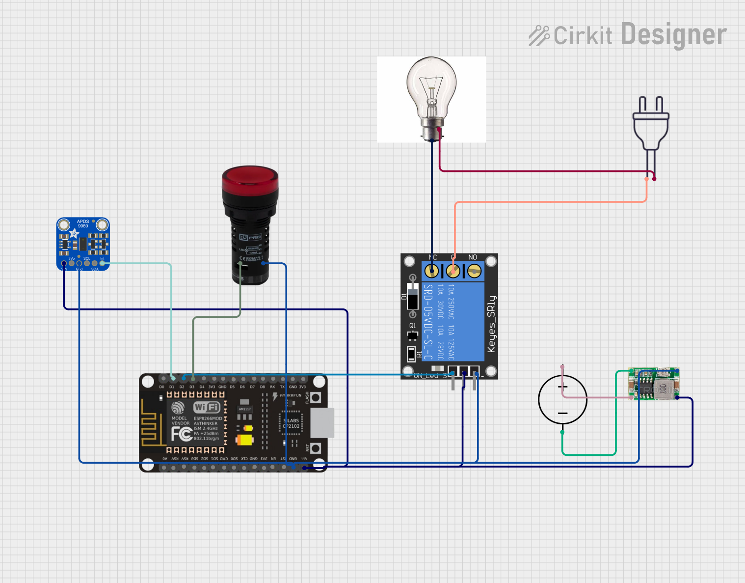
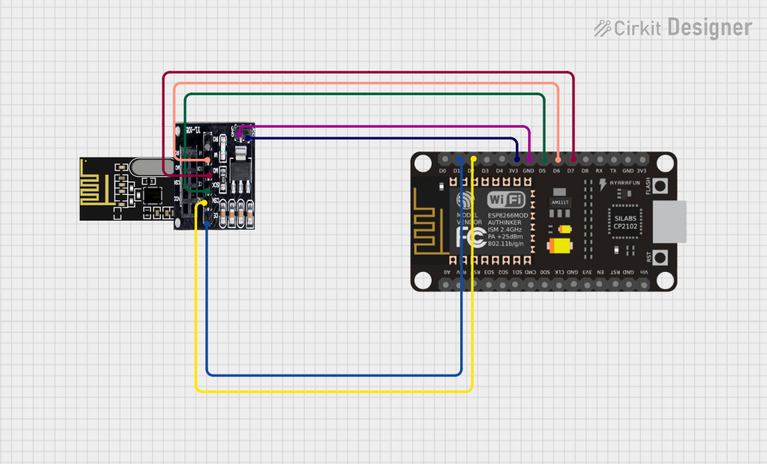
Explore Projects Built with ESP-01S Porgramer-Adapter
Common Applications and Use Cases
- Uploading firmware to ESP-01S Wi-Fi modules
- Debugging and testing ESP-01S-based projects
- Prototyping IoT applications
- Educational purposes for learning about ESP8266-based modules
Technical Specifications
Key Technical Details
- Input Voltage: 5V (via USB interface)
- Output Voltage: 3.3V (regulated for ESP-01S module)
- Interface: USB Type-A
- Compatibility: ESP-01S Wi-Fi module
- Dimensions: 48mm x 18mm x 10mm
- LED Indicators: Power and communication status
- Onboard Components: CH340 USB-to-Serial chip, voltage regulator, and reset circuitry
Pin Configuration and Descriptions
The ESP-01S Programmer-Adapter has a socket for the ESP-01S module. Below is the pin mapping for the adapter:
| Pin Name | Description |
|---|---|
| VCC | Supplies 3.3V power to the ESP-01S module |
| GND | Ground connection |
| TXD | Transmit data (connected to CH340 TX) |
| RXD | Receive data (connected to CH340 RX) |
| GPIO0 | Used for programming mode selection |
| RESET | Resets the ESP-01S module |
Usage Instructions
How to Use the ESP-01S Programmer-Adapter
Insert the ESP-01S Module:
- Align the pins of the ESP-01S module with the socket on the programmer-adapter.
- Ensure the module is firmly seated in the socket.
Connect to a Computer:
- Plug the programmer-adapter into a USB port on your computer.
- The power LED on the adapter should light up, indicating proper connection.
Install Drivers:
- If your computer does not recognize the adapter, install the CH340 USB-to-Serial driver. The driver can be downloaded from the manufacturer's website or other trusted sources.
Enter Programming Mode:
- To upload firmware, ensure the GPIO0 pin is pulled LOW (this is typically handled automatically by the adapter).
Upload Firmware:
- Use an IDE like Arduino IDE or a dedicated ESP8266 flashing tool.
- Select the correct COM port and board type (e.g., "Generic ESP8266 Module").
- Upload your code or firmware.
Test and Debug:
- After uploading, the ESP-01S module will reset and run the uploaded firmware.
- Use the serial monitor in your IDE to debug or monitor output.
Important Considerations and Best Practices
- Voltage Compatibility: The adapter regulates the USB 5V input to 3.3V for the ESP-01S module. Do not connect external 5V power directly to the ESP-01S module.
- Driver Installation: Ensure the CH340 driver is correctly installed to avoid communication issues.
- Proper Insertion: Double-check the orientation of the ESP-01S module when inserting it into the adapter to prevent damage.
- Firmware Uploading: Always verify the correct COM port and board settings in your IDE before uploading firmware.
Example Code for Arduino IDE
Below is an example sketch to test the ESP-01S module using the programmer-adapter:
// Example code to test ESP-01S module with Arduino IDE
// This code sets up the ESP-01S as a Wi-Fi access point

#include <ESP8266WiFi.h> // Include the ESP8266 Wi-Fi library

void setup() {
  Serial.begin(115200); // Initialize serial communication at 115200 baud
  Serial.println(); // Print a blank line for readability

  // Set up the ESP-01S as a Wi-Fi access point
  WiFi.softAP("ESP-01S_Test", "password123"); // SSID and password
  Serial.println("Access Point Started");
  Serial.print("IP Address: ");
  Serial.println(WiFi.softAPIP()); // Print the IP address of the access point
}

void loop() {
  // Keep the program running
}
Troubleshooting and FAQs
Common Issues and Solutions
| Issue | Solution |
|---|---|
| Adapter not recognized by the computer | Install or update the CH340 USB-to-Serial driver. |
| ESP-01S module not detected during upload | Ensure GPIO0 is pulled LOW and the module is properly seated in the socket. |
| Power LED not lighting up | Check the USB connection and ensure the adapter is receiving power. |
| Firmware upload fails | Verify the correct COM port and board settings in the IDE. |
| Serial monitor shows garbled output | Ensure the baud rate in the serial monitor matches the baud rate in the code. |
FAQs
Can I use this adapter with an ESP-01 module (non-S version)?
- Yes, the adapter is compatible with both ESP-01 and ESP-01S modules.
Do I need an external power supply for the ESP-01S module?
- No, the adapter provides regulated 3.3V power to the module via USB.
What is the purpose of the GPIO0 pin?
- The GPIO0 pin is used to switch the ESP-01S module between normal operation mode and programming mode.
Can I use this adapter for continuous operation of the ESP-01S module?
- While the adapter can power the module for testing and debugging, it is not recommended for long-term deployment in a project.
Where can I download the CH340 driver?
- The driver can be downloaded from the Wishiot website or other trusted sources like the official CH340 driver page.
By following this documentation, you can effectively use the ESP-01S Programmer-Adapter for your ESP-01S module projects.