How to Use Servo: Examples, Pinouts, and Specs
Introduction
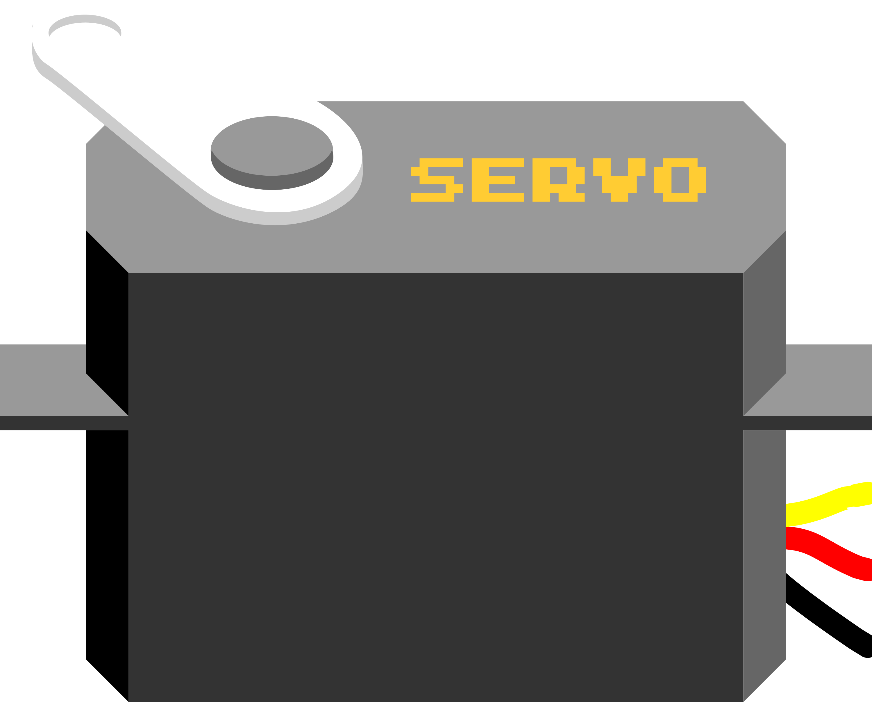
A servo is a rotary actuator that allows for precise control of angular position, velocity, and acceleration. It consists of a motor coupled to a sensor for position feedback, along with a control circuit. Servos are widely used in robotics, automation, remote-controlled vehicles, and other applications requiring precise movement and positioning.
Explore Projects Built with Servo

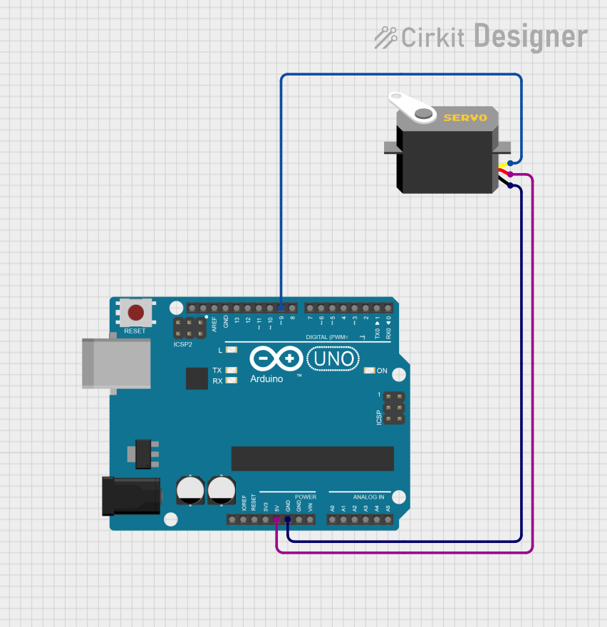
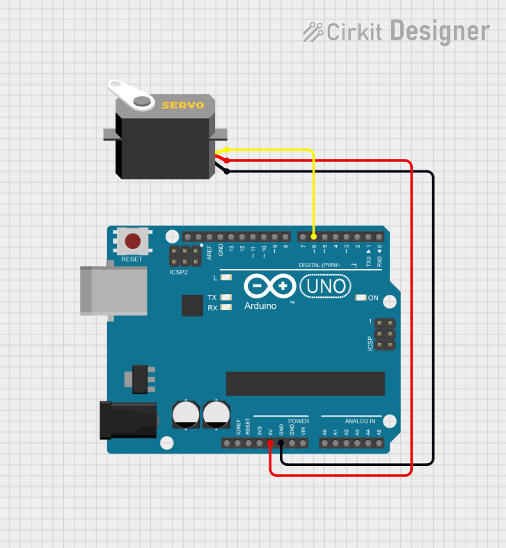
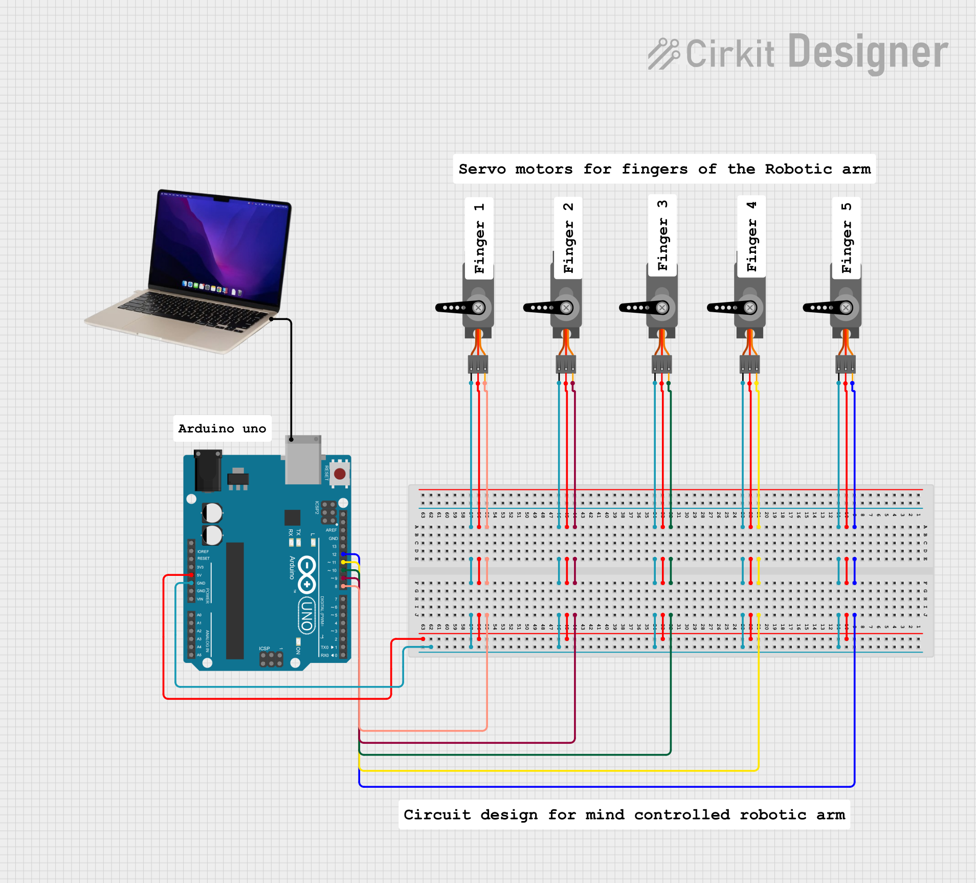
Explore Projects Built with Servo
Common Applications and Use Cases
- Robotics: For controlling robotic arms, grippers, and joints.
- Remote-controlled vehicles: Steering mechanisms and throttle control.
- Automation: Conveyor belts, sorting systems, and industrial machinery.
- Hobby projects: Model airplanes, boats, and cars.
- Camera gimbals: For stabilizing and positioning cameras.
Technical Specifications
Below are the general technical specifications for a standard hobby servo. Note that specifications may vary depending on the specific model and manufacturer.
| Parameter | Value |
|---|---|
| Operating Voltage | 4.8V to 6V |
| Stall Torque | ~1.5 kg.cm to 20 kg.cm (varies) |
| Operating Speed | ~0.1s to 0.2s per 60° (varies) |
| Control Signal | PWM (Pulse Width Modulation) |
| PWM Signal Range | 1ms to 2ms (typical) |
| Angle Range | 0° to 180° (typical) |
| Idle Current | ~10mA to 20mA |
| Stall Current | ~1A to 2A (varies) |
Pin Configuration
Servos typically have three wires for connection. The pinout is as follows:
| Wire Color | Function | Description |
|---|---|---|
| Red | VCC (Power) | Connect to a 5V or 6V power supply. |
| Black/Brown | GND (Ground) | Connect to the ground of the circuit. |
| Yellow/Orange | Signal (PWM Input) | Receives the PWM signal for control. |
Usage Instructions
How to Use a Servo in a Circuit
- Power the Servo: Connect the red wire to a 5V or 6V power source and the black/brown wire to ground.
- Control Signal: Connect the yellow/orange wire to a PWM-capable pin on your microcontroller (e.g., Arduino).
- Generate PWM Signal: Use a PWM signal to control the servo's position. A pulse width of 1ms typically moves the servo to 0°, 1.5ms to 90°, and 2ms to 180°.
Important Considerations and Best Practices
- Power Supply: Ensure the power supply can handle the servo's stall current to avoid voltage drops.
- Decoupling Capacitor: Add a capacitor (e.g., 100µF) across the power supply to stabilize voltage.
- Avoid Overloading: Do not exceed the servo's torque rating to prevent damage.
- PWM Frequency: Use a PWM frequency of 50Hz (20ms period) for standard servos.
- Mechanical Limits: Avoid forcing the servo beyond its physical limits to prevent damage.
Example: Controlling a Servo with Arduino UNO
Below is an example code to control a servo using an Arduino UNO:
#include <Servo.h> // Include the Servo library

Servo myServo; // Create a Servo object

void setup() {
  myServo.attach(9); // Attach the servo to pin 9
}

void loop() {
  myServo.write(0); // Move servo to 0 degrees
  delay(1000);      // Wait for 1 second

  myServo.write(90); // Move servo to 90 degrees
  delay(1000);       // Wait for 1 second

  myServo.write(180); // Move servo to 180 degrees
  delay(1000);        // Wait for 1 second
}
Code Explanation
- The
Servolibrary simplifies servo control. - The
attach()function links the servo to a specific PWM pin. - The
write()function sets the servo's position in degrees (0° to 180°). - Delays are used to allow the servo to reach the desired position.
Troubleshooting and FAQs
Common Issues and Solutions
Servo Not Moving
- Cause: Incorrect wiring or insufficient power supply.
- Solution: Double-check connections and ensure the power supply meets the servo's requirements.
Jittery Movement
- Cause: Electrical noise or unstable power supply.
- Solution: Add a decoupling capacitor across the power supply and ensure proper grounding.
Overheating
- Cause: Prolonged stalling or overloading.
- Solution: Avoid exceeding the servo's torque rating and ensure it is not mechanically blocked.
Limited Range of Motion
- Cause: PWM signal out of range or mechanical limits.
- Solution: Verify the PWM signal range (1ms to 2ms) and ensure the servo is not obstructed.
FAQs
Q: Can I power a servo directly from the Arduino?
A: It is not recommended, as the Arduino's 5V pin cannot supply enough current for most servos. Use an external power supply.
Q: How do I control multiple servos with an Arduino?
A: Use the Servo library to create multiple Servo objects and attach each to a different PWM pin.
Q: Can I rotate a servo continuously?
A: Standard servos have a limited range (0° to 180°). For continuous rotation, use a continuous rotation servo.
Q: What happens if I send a PWM signal outside the 1ms to 2ms range?
A: The servo may attempt to move beyond its physical limits, potentially causing damage. Always stay within the specified range.