Cirkit Designer Logo
Cirkit Designer
Your all-in-one circuit design IDE
Home / 
Component Documentation

How to Use LED RGB Strip: Examples, Pinouts, and Specs

Image of LED RGB Strip
Cirkit Designer LogoDesign with LED RGB Strip in Cirkit Designer

Introduction

An LED RGB Strip is a flexible circuit board populated with Light Emitting Diodes (LEDs) that can emit red, green, and blue light. These strips are widely used for ambient lighting, accent lighting, and creative DIY projects due to their versatility and ease of use. They can be found in residential, commercial, and industrial settings, enhancing the aesthetics of spaces or serving functional lighting purposes.

Explore Projects Built with LED RGB Strip

Use Cirkit Designer to design, explore, and prototype these projects online. Some projects support real-time simulation. Click "Open Project" to start designing instantly!
Arduino-Controlled RGB LED Strip Lighting System with 220V to 24V Power Transformer
Image of asd: A project utilizing LED RGB Strip in a practical application
This circuit controls multiple RGB LED strips using an Arduino UNO, powered by a 220V to 24V transformer. The Arduino is programmed to turn the RGB LEDs on and off in a sequence, with each color channel (red, green, blue) connected to specific digital output pins on the Arduino.
Cirkit Designer LogoOpen Project in Cirkit Designer
RGB LED Strip Color Controller with Potentiometers and Power Switch
Image of potbased decoration: A project utilizing LED RGB Strip in a practical application
This circuit controls an RGB LED strip using three potentiometers, each potentiometer likely adjusts the intensity of one color channel (red, green, blue) of the LED strip. A rocker switch is used to power the circuit on and off, and an 18650 Li-Ion battery provides the power source. The common connection of the LED strip is connected to the negative terminal of the battery, while the positive terminal goes through the rocker switch to the potentiometers and then to the individual color channels.
Cirkit Designer LogoOpen Project in Cirkit Designer
Arduino Mega 2560 and Raspberry Pi 4B Controlled WS2812 RGB LED Strip
Image of circuit_image: A project utilizing LED RGB Strip in a practical application
This circuit features an Arduino Mega 2560 microcontroller programmed to control a WS2812 RGB LED strip and a white LED, indicating status or providing user feedback. The Arduino and the LED strip are powered by a common 5V supply, and the circuit includes interfacing with a Raspberry Pi 4B for potential communication or coordination between the two boards.
Cirkit Designer LogoOpen Project in Cirkit Designer
Wi-Fi Controlled LED Strip with Wemos D1 Mini and IKEA Trådfri Driver
Image of WLED Diskbänken: A project utilizing LED RGB Strip in a practical application
This circuit is designed to control a WS2812 RGB LED strip using a Wemos D1 Mini microcontroller running WLED software. The circuit includes an IKEA Trådfri LED driver that converts 24V to 5V via an LM2596 voltage regulator, and an nMOS transistor to switch the LED strip's ground connection. The setup is intended for lighting applications, such as under-cabinet lighting in a kitchen.
Cirkit Designer LogoOpen Project in Cirkit Designer

Explore Projects Built with LED RGB Strip

Use Cirkit Designer to design, explore, and prototype these projects online. Some projects support real-time simulation. Click "Open Project" to start designing instantly!
Image of asd: A project utilizing LED RGB Strip in a practical application
Arduino-Controlled RGB LED Strip Lighting System with 220V to 24V Power Transformer
This circuit controls multiple RGB LED strips using an Arduino UNO, powered by a 220V to 24V transformer. The Arduino is programmed to turn the RGB LEDs on and off in a sequence, with each color channel (red, green, blue) connected to specific digital output pins on the Arduino.
Cirkit Designer LogoOpen Project in Cirkit Designer
Image of potbased decoration: A project utilizing LED RGB Strip in a practical application
RGB LED Strip Color Controller with Potentiometers and Power Switch
This circuit controls an RGB LED strip using three potentiometers, each potentiometer likely adjusts the intensity of one color channel (red, green, blue) of the LED strip. A rocker switch is used to power the circuit on and off, and an 18650 Li-Ion battery provides the power source. The common connection of the LED strip is connected to the negative terminal of the battery, while the positive terminal goes through the rocker switch to the potentiometers and then to the individual color channels.
Cirkit Designer LogoOpen Project in Cirkit Designer
Image of circuit_image: A project utilizing LED RGB Strip in a practical application
Arduino Mega 2560 and Raspberry Pi 4B Controlled WS2812 RGB LED Strip
This circuit features an Arduino Mega 2560 microcontroller programmed to control a WS2812 RGB LED strip and a white LED, indicating status or providing user feedback. The Arduino and the LED strip are powered by a common 5V supply, and the circuit includes interfacing with a Raspberry Pi 4B for potential communication or coordination between the two boards.
Cirkit Designer LogoOpen Project in Cirkit Designer
Image of WLED Diskbänken: A project utilizing LED RGB Strip in a practical application
Wi-Fi Controlled LED Strip with Wemos D1 Mini and IKEA Trådfri Driver
This circuit is designed to control a WS2812 RGB LED strip using a Wemos D1 Mini microcontroller running WLED software. The circuit includes an IKEA Trådfri LED driver that converts 24V to 5V via an LM2596 voltage regulator, and an nMOS transistor to switch the LED strip's ground connection. The setup is intended for lighting applications, such as under-cabinet lighting in a kitchen.
Cirkit Designer LogoOpen Project in Cirkit Designer

Technical Specifications

Key Technical Details

  • Voltage: Typically 5V, 12V, or 24V DC
  • Current: Varies depending on the length of the strip and the number of LEDs per meter
  • Power Ratings: Typically ranges from 4.8W to 14.4W per meter
  • Color Range: 16 million colors with appropriate controller
  • Lifespan: Approximately 25,000 to 50,000 hours

Pin Configuration and Descriptions

Pin Description
VCC Power supply (positive)
GND Ground (negative)
DI Data input for addressable strips
DO Data output for connecting additional strips (addressable strips)
R Red color control (for non-addressable strips)
G Green color control (for non-addressable strips)
B Blue color control (for non-addressable strips)

Usage Instructions

How to Use the Component in a Circuit

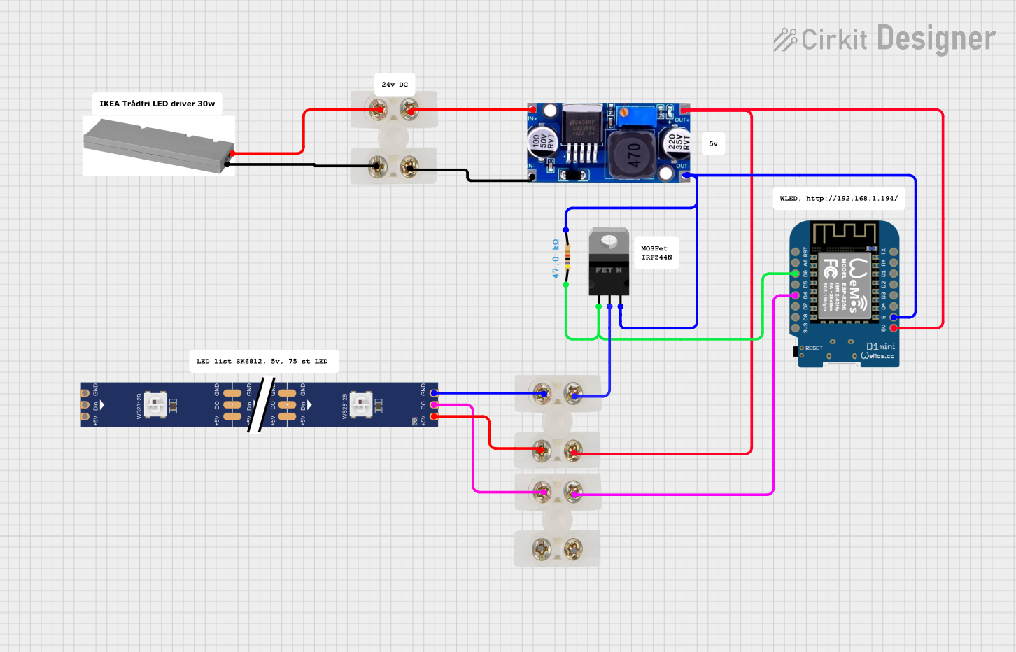
  1. Power Supply Connection: Connect the VCC and GND pins to a suitable power supply, ensuring the voltage matches the strip's requirements.
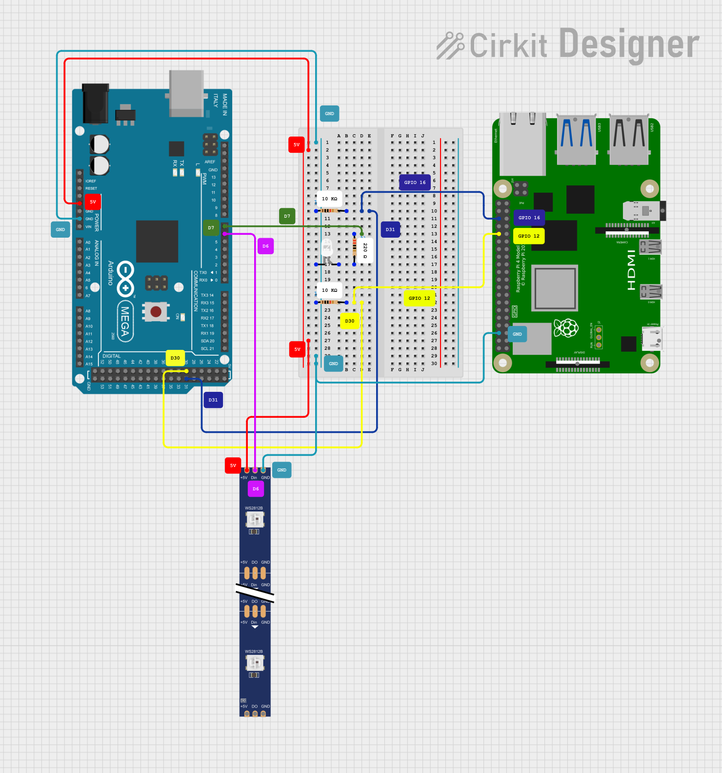
  2. Data Signal Connection (for addressable strips): Connect the DI pin to a digital output on a microcontroller, such as an Arduino UNO.
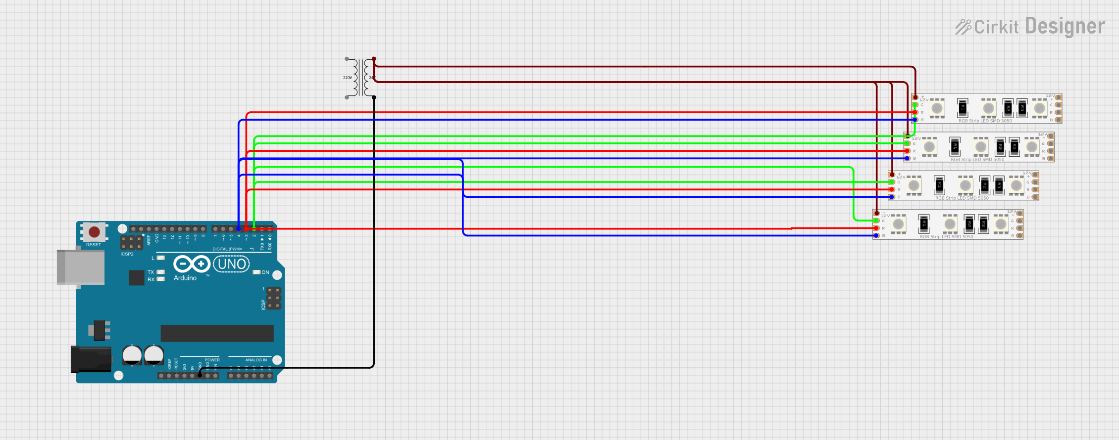
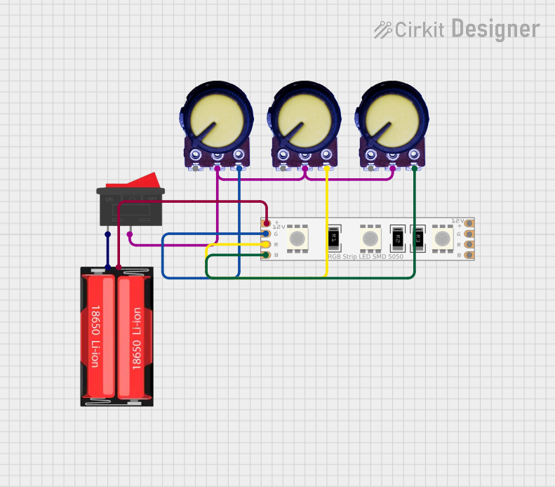
  3. Color Control (for non-addressable strips): Connect the R, G, and B pins to PWM-capable digital outputs on a microcontroller for color mixing.

Important Considerations and Best Practices

  • Current Limiting: Use appropriate resistors or a constant current power supply to prevent overdriving the LEDs.
  • Heat Dissipation: Ensure adequate ventilation or heat sinking to prevent overheating.
  • Voltage Drop: For longer strips, be aware of voltage drop issues and power the strip at multiple points if necessary.
  • Waterproofing: If used outdoors, ensure the strip has an appropriate IP rating for weather resistance.

Example Code for Arduino UNO

// Example code to control an addressable RGB LED Strip with an Arduino UNO

#include <FastLED.h>

#define LED_PIN     6
#define NUM_LEDS    30
#define BRIGHTNESS  64
#define LED_TYPE    WS2812B
#define COLOR_ORDER GRB
CRGB leds[NUM_LEDS];

void setup() {
  FastLED.addLeds<LED_TYPE, LED_PIN, COLOR_ORDER>(leds, NUM_LEDS)
          .setCorrection(TypicalLEDStrip);
  FastLED.setBrightness(BRIGHTNESS);
}

void loop() {
  // Fill the dots one after the other with a color
  for(int i = 0; i < NUM_LEDS; i++) {
    leds[i] = CRGB::White;
    FastLED.show();
    delay(30);
    leds[i] = CRGB::Black;
  }
}

Note: The above code uses the FastLED library to control addressable RGB LED strips. It lights up each LED in sequence. Make sure to install the FastLED library through the Arduino Library Manager before uploading this sketch.

Troubleshooting and FAQs

Common Issues

  • LEDs Not Lighting Up: Check power supply connections and ensure the voltage is correct. Verify that the data signal is connected to the correct pin.
  • Incorrect Colors: Ensure the COLOR_ORDER in the code matches the strip's specifications. Adjust the RGB values accordingly.
  • Dim or Flickering LEDs: This could be due to insufficient power or a long strip causing voltage drop. Power the strip at multiple points or use a higher current power supply.

Solutions and Tips for Troubleshooting

  • Power Issues: Use a multimeter to check the voltage at the start and end of the strip.
  • Signal Issues: Ensure that the data line is not too long and is properly shielded if necessary.
  • Code Issues: Double-check the code for any errors and ensure the correct library and board settings are used.

FAQs:

  • Q: Can I cut the LED strip to size?

    • A: Yes, LED strips typically have cut marks along the strip. Cut only along these marks to avoid damaging the LEDs.
  • Q: How do I connect multiple strips together?

    • A: For addressable strips, connect the DO of the first strip to the DI of the next strip. For non-addressable strips, connect all R, G, B, and power lines in parallel.
  • Q: Can I control the strip with a remote?

    • A: Yes, there are controllers available that can be used with a remote. Make sure the controller is compatible with your LED strip type.