How to Use UWB: Examples, Pinouts, and Specs
Introduction
Ultra-Wideband (UWB) is a radio technology that operates over a wide frequency spectrum, typically greater than 500 MHz. It is designed for short-range, high-bandwidth communications, making it ideal for applications requiring precise location tracking and fast data transmission. UWB is widely used in Internet of Things (IoT) devices, automotive systems, smart home technologies, and industrial automation.
Explore Projects Built with UWB


Explore Projects Built with UWB
Common Applications:
- Precise Location Tracking: UWB is used in real-time location systems (RTLS) for tracking objects or people with centimeter-level accuracy.
- Automotive Systems: Enables secure keyless entry and in-car communication.
- IoT Devices: Facilitates seamless communication between smart devices.
- Consumer Electronics: Used in smartphones, wearables, and smart tags for proximity-based interactions.
- Industrial Automation: Provides accurate positioning for robotics and asset tracking.
Technical Specifications
Below are the key technical details of UWB technology:
| Parameter | Specification |
|---|---|
| Frequency Range | 3.1 GHz to 10.6 GHz (regulated by region) |
| Bandwidth | Minimum 500 MHz |
| Data Rate | Up to 27 Mbps (depending on implementation) |
| Range | Typically 10-50 meters (varies with environment and power settings) |
| Positioning Accuracy | ±10 cm (depending on system configuration) |
| Transmission Power | ≤ -41.3 dBm/MHz (FCC regulation for unlicensed use) |
| Modulation Techniques | Pulse-based or Orthogonal Frequency Division Multiplexing (OFDM) |
| Communication Protocols | IEEE 802.15.4z (latest standard for secure UWB communication) |
| Power Consumption | Low power, suitable for battery-operated devices |
Pin Configuration and Descriptions
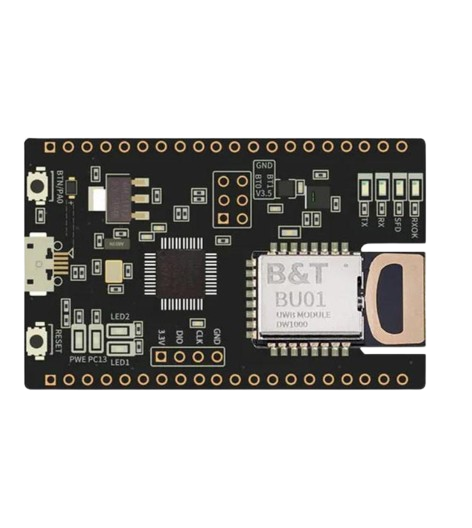
UWB modules typically come with a set of pins for interfacing with microcontrollers or other devices. Below is an example pinout for a generic UWB module:
| Pin | Name | Description |
|---|---|---|
| 1 | VCC | Power supply input (typically 3.3V or 5V, depending on the module) |
| 2 | GND | Ground connection |
| 3 | TX | Transmit data pin |
| 4 | RX | Receive data pin |
| 5 | SPI_CLK | SPI clock signal for communication |
| 6 | SPI_MOSI | SPI Master Out Slave In (data input to the module) |
| 7 | SPI_MISO | SPI Master In Slave Out (data output from the module) |
| 8 | RESET | Reset pin to restart the module |
| 9 | IRQ | Interrupt request pin for signaling events |
| 10 | GPIO | General-purpose input/output pin for custom configurations |
Note: Pin configurations may vary depending on the specific UWB module. Always refer to the manufacturer's datasheet for exact details.
Usage Instructions
How to Use UWB in a Circuit
- Power Supply: Connect the VCC and GND pins to a stable power source (e.g., 3.3V or 5V).
- Communication Interface: Use SPI or UART to interface the UWB module with a microcontroller (e.g., Arduino UNO).
- Antenna Connection: Ensure the module's antenna is properly connected for optimal signal transmission and reception.
- Initialization: Configure the UWB module using the appropriate communication protocol (e.g., IEEE 802.15.4z).
- Data Transmission: Use the TX and RX pins for sending and receiving data, or SPI for high-speed communication.
- Positioning: For location tracking, deploy multiple UWB modules as anchors and configure them to calculate distances using time-of-flight (ToF) measurements.
Important Considerations:
- Regulatory Compliance: Ensure the UWB module complies with local frequency regulations.
- Line of Sight: For best performance, maintain a clear line of sight between UWB devices.
- Interference: Avoid placing the module near sources of electromagnetic interference (e.g., Wi-Fi routers).
- Power Management: Use low-power modes to extend battery life in portable applications.
Example: Using UWB with Arduino UNO
Below is an example code snippet for interfacing a UWB module with an Arduino UNO via SPI:
#include <SPI.h>

// Define SPI pins for Arduino UNO
#define CS_PIN 10  // Chip Select pin
#define IRQ_PIN 2  // Interrupt pin
#define RESET_PIN 9 // Reset pin

void setup() {
  // Initialize serial communication for debugging
  Serial.begin(9600);

  // Initialize SPI communication
  SPI.begin();

  // Configure pins
  pinMode(CS_PIN, OUTPUT);
  pinMode(IRQ_PIN, INPUT);
  pinMode(RESET_PIN, OUTPUT);

  // Reset the UWB module
  digitalWrite(RESET_PIN, LOW);
  delay(10); // Wait for 10ms
  digitalWrite(RESET_PIN, HIGH);

  Serial.println("UWB module initialized.");
}

void loop() {
  // Example: Send data to UWB module
  digitalWrite(CS_PIN, LOW); // Select the UWB module
  SPI.transfer(0x01); // Example command to send
  digitalWrite(CS_PIN, HIGH); // Deselect the UWB module

  // Example: Read data from UWB module
  digitalWrite(CS_PIN, LOW);
  byte response = SPI.transfer(0x00); // Example command to read
  digitalWrite(CS_PIN, HIGH);

  // Print the response
  Serial.print("Response: ");
  Serial.println(response, HEX);

  delay(1000); // Wait for 1 second
}
Note: Replace the example commands (0x01 and 0x00) with actual commands based on the UWB module's datasheet.
Troubleshooting and FAQs
Common Issues:
No Communication with the Module:
- Cause: Incorrect wiring or SPI configuration.
- Solution: Double-check the connections and ensure the SPI pins are correctly defined in the code.
Poor Range or Accuracy:
- Cause: Obstructions or interference in the environment.
- Solution: Ensure a clear line of sight and minimize interference from other devices.
Module Not Powering On:
- Cause: Insufficient power supply or incorrect voltage.
- Solution: Verify the power supply voltage matches the module's requirements.
Unexpected Data or Errors:
- Cause: Incorrect initialization or communication settings.
- Solution: Review the module's datasheet and ensure proper configuration.
FAQs:
Q: Can UWB work through walls?
- A: UWB signals can penetrate walls, but the range and accuracy may be reduced.
Q: Is UWB secure for data transmission?
- A: Yes, UWB uses short pulses and secure protocols like IEEE 802.15.4z, making it highly secure.
Q: Can I use UWB with other wireless technologies?
- A: Yes, UWB can coexist with other wireless technologies like Wi-Fi and Bluetooth due to its low power and wide frequency range.
Q: What is the maximum range of UWB?
- A: The typical range is 10-50 meters, depending on the environment and power settings.
By following this documentation, users can effectively integrate UWB technology into their projects and troubleshoot common issues. Always refer to the specific module's datasheet for detailed information.