How to Use 2-Channel 12V Relay Module: Examples, Pinouts, and Specs
Introduction
The 2-Channel 12V Relay Module is an electronic component designed to control two independent circuits using a 12V power supply. It acts as an interface between low-power control systems (e.g., microcontrollers like Arduino) and high-power devices, such as motors, lights, or appliances. This module enables the safe switching of high-voltage or high-current loads using low-voltage control signals.
Explore Projects Built with 2-Channel 12V Relay Module


Explore Projects Built with 2-Channel 12V Relay Module
Common Applications and Use Cases
- Home automation systems (e.g., controlling lights, fans, or appliances)
- Industrial automation for switching high-power devices
- Robotics and motor control
- IoT projects requiring high-voltage device control
- Security systems (e.g., activating alarms or locks)
Technical Specifications
Key Technical Details
- Operating Voltage (Control Side): 12V DC
- Relay Output Voltage: 250V AC (max) or 30V DC (max)
- Relay Output Current: 10A (max)
- Trigger Voltage (Input Signal): 3-12V DC (logic low trigger)
- Number of Channels: 2
- Isolation: Optocoupler isolation for safe operation
- Dimensions: ~50mm x 40mm x 20mm
- Indicator LEDs: Onboard LEDs for relay status indication
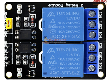
Pin Configuration and Descriptions
The 2-Channel 12V Relay Module has two main sections: the input (control) side and the output (load) side.
Input (Control) Pins
| Pin Name | Description |
|---|---|
| VCC | Connect to the 12V DC power supply (positive terminal). |
| GND | Connect to the ground of the power supply. |
| IN1 | Control signal for Relay 1. A logic LOW (0V) activates the relay. |
| IN2 | Control signal for Relay 2. A logic LOW (0V) activates the relay. |
Output (Load) Terminals
Each relay has three output terminals: COM, NO, and NC.
| Terminal Name | Description |
|---|---|
| COM | Common terminal. Connect to the power source or load. |
| NO | Normally Open terminal. Connect to the load if you want it OFF by default. |
| NC | Normally Closed terminal. Connect to the load if you want it ON by default. |
Usage Instructions
How to Use the Component in a Circuit
Power the Module:
- Connect the VCC pin to a 12V DC power supply and the GND pin to the ground.
- Ensure the power supply can provide sufficient current for the relays (typically ~70mA per relay).
Connect the Control Signals:
- Connect the IN1 and IN2 pins to the control signals from a microcontroller (e.g., Arduino).
- A logic LOW (0V) on IN1 or IN2 will activate the corresponding relay.
Connect the Load:
- Identify whether the load should be connected to the NO or NC terminal based on the desired default state.
- Connect the power source and load to the appropriate terminals (COM, NO, or NC).
Test the Circuit:
- When the control signal is LOW, the relay will activate, switching the load between the COM and NO terminals.
Important Considerations and Best Practices
- Isolation: The module uses optocouplers for isolation, but ensure proper grounding between the control and load circuits.
- Load Ratings: Do not exceed the maximum voltage (250V AC or 30V DC) or current (10A) ratings of the relays.
- Flyback Diodes: For inductive loads (e.g., motors), use flyback diodes across the load to protect the relay from voltage spikes.
- Power Supply: Use a stable 12V DC power supply to avoid relay malfunction.
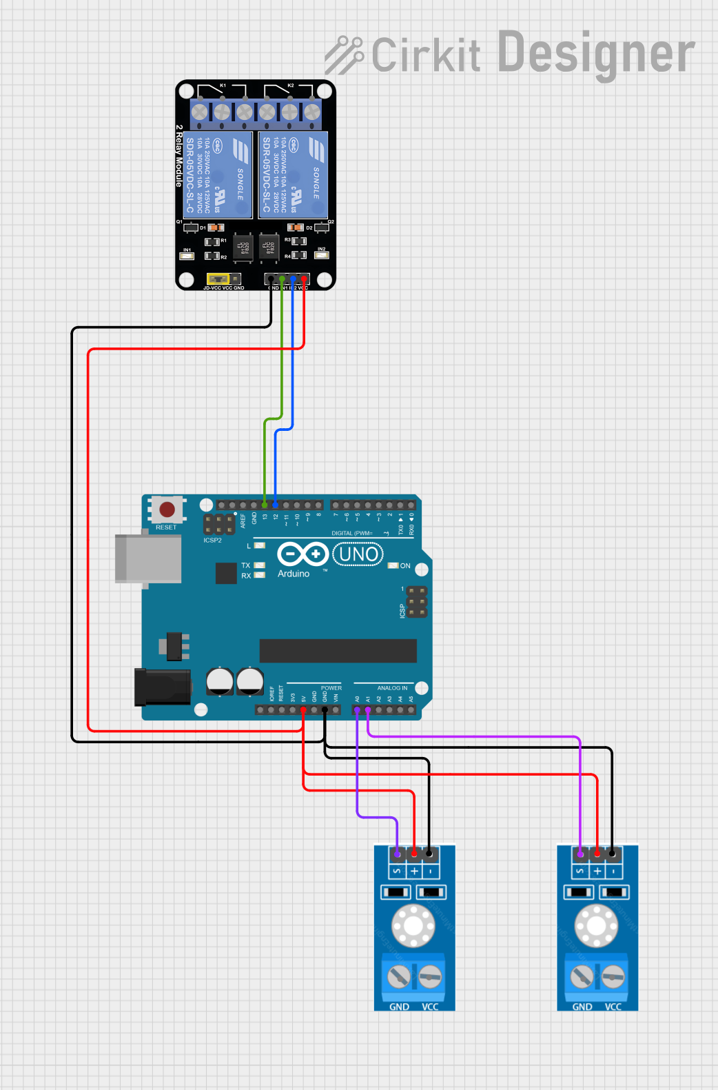
Example: Connecting to an Arduino UNO
Below is an example of how to control the 2-Channel 12V Relay Module using an Arduino UNO.
Circuit Connections
- Connect the module's VCC to the Arduino's 12V power supply.
- Connect the module's GND to the Arduino's GND.
- Connect IN1 to Arduino digital pin 7 and IN2 to Arduino digital pin 8.
Arduino Code
// Define the relay control pins
const int relay1 = 7; // Relay 1 connected to digital pin 7
const int relay2 = 8; // Relay 2 connected to digital pin 8

void setup() {
  // Set relay pins as outputs
  pinMode(relay1, OUTPUT);
  pinMode(relay2, OUTPUT);

  // Initialize relays to OFF state (HIGH signal)
  digitalWrite(relay1, HIGH);
  digitalWrite(relay2, HIGH);
}

void loop() {
  // Turn Relay 1 ON
  digitalWrite(relay1, LOW); // LOW signal activates the relay
  delay(2000); // Wait for 2 seconds

  // Turn Relay 1 OFF
  digitalWrite(relay1, HIGH); // HIGH signal deactivates the relay
  delay(2000); // Wait for 2 seconds

  // Turn Relay 2 ON
  digitalWrite(relay2, LOW);
  delay(2000);

  // Turn Relay 2 OFF
  digitalWrite(relay2, HIGH);
  delay(2000);
}
Troubleshooting and FAQs
Common Issues and Solutions
Relays Not Activating:
- Ensure the module is powered with a stable 12V DC supply.
- Verify that the control signals (IN1/IN2) are correctly connected and set to logic LOW.
Load Not Switching:
- Check the wiring of the load to the COM, NO, and NC terminals.
- Ensure the load does not exceed the relay's voltage or current ratings.
Relay Clicking Noise:
- This may indicate an unstable power supply. Use a regulated 12V DC source.
Arduino Resetting When Relays Activate:
- The relays may draw too much current, causing voltage drops. Use a separate 12V power supply for the relay module.
FAQs
Q: Can I use a 5V power supply instead of 12V?
A: No, this module is designed specifically for 12V operation. Using a lower voltage may cause malfunction.
Q: Can I control AC and DC loads simultaneously?
A: Yes, as long as each load is connected to a separate relay and does not exceed the relay's ratings.
Q: Is it safe to use this module with high-voltage devices?
A: Yes, but ensure proper insulation and safety precautions when working with high voltages.