Cirkit Designer Logo
Cirkit Designer
Your all-in-one circuit design IDE
Home / 
Component Documentation

How to Use SparkFun Photon RedBoard: Examples, Pinouts, and Specs

Image of SparkFun Photon RedBoard
Cirkit Designer LogoDesign with SparkFun Photon RedBoard in Cirkit Designer

Introduction

The SparkFun Photon RedBoard is an innovative development board that integrates the Particle Photon Wi-Fi module, offering a seamless experience for prototyping Wi-Fi enabled projects. This board is designed to be compatible with the Arduino form factor, allowing for a wide range of applications ranging from Internet of Things (IoT) devices to smart home automation and wireless sensor networks.

Explore Projects Built with SparkFun Photon RedBoard

Use Cirkit Designer to design, explore, and prototype these projects online. Some projects support real-time simulation. Click "Open Project" to start designing instantly!
SparkFun RedBoard Controlled Multi-Servo Circuit
Image of Sassy-Display: A project utilizing SparkFun Photon RedBoard in a practical application
This circuit consists of a SparkFun RedBoard, which is an Arduino-compatible development platform, connected to four servo motors. The RedBoard provides 5V power and ground to each servo, and it also controls the servos using PWM signals on pins D3, D4, D5, and D6. The purpose of this circuit is to independently control the position or speed of four servos, commonly used in robotics and RC applications.
Cirkit Designer LogoOpen Project in Cirkit Designer
Battery-Powered Smart Light with Proximity Sensor and OLED Display using Adafruit QT Py RP2040
Image of lab: A project utilizing SparkFun Photon RedBoard in a practical application
This circuit is a portable, battery-powered system featuring an Adafruit QT Py RP2040 microcontroller that interfaces with an OLED display, a proximity sensor, an accelerometer, and an RGB LED strip. The system is powered by a lithium-ion battery with a step-up boost converter to provide 5V for the LED strip, and it includes a toggle switch for power control. The microcontroller communicates with the sensors and display via I2C.
Cirkit Designer LogoOpen Project in Cirkit Designer
Photon 2 Motion Detector Alarm with PIR Sensor and Wi-Fi Control
Image of final project: A project utilizing SparkFun Photon RedBoard in a practical application
This circuit is a motion-activated alarm system using a Photon microcontroller, a PIR sensor, a piezo buzzer, a red LED, and a pushbutton. When motion is detected by the PIR sensor, the red LED lights up and the buzzer sounds an alarm, which can be deactivated manually via the pushbutton or remotely through the Particle Cloud.
Cirkit Designer LogoOpen Project in Cirkit Designer
Arduino and MCP2515 CAN Bus Communication with LED Indicators
Image of ConnectionDiagram_COM3_Part1: A project utilizing SparkFun Photon RedBoard in a practical application
This circuit consists of two Arduino UNOs and a SparkFun RedBoard, each interfaced with MCP2515 CAN controllers for communication. Additionally, the circuit includes multiple LEDs with current-limiting resistors, which are controlled by the microcontrollers to indicate various states or activities.
Cirkit Designer LogoOpen Project in Cirkit Designer

Explore Projects Built with SparkFun Photon RedBoard

Use Cirkit Designer to design, explore, and prototype these projects online. Some projects support real-time simulation. Click "Open Project" to start designing instantly!
Image of Sassy-Display: A project utilizing SparkFun Photon RedBoard in a practical application
SparkFun RedBoard Controlled Multi-Servo Circuit
This circuit consists of a SparkFun RedBoard, which is an Arduino-compatible development platform, connected to four servo motors. The RedBoard provides 5V power and ground to each servo, and it also controls the servos using PWM signals on pins D3, D4, D5, and D6. The purpose of this circuit is to independently control the position or speed of four servos, commonly used in robotics and RC applications.
Cirkit Designer LogoOpen Project in Cirkit Designer
Image of lab: A project utilizing SparkFun Photon RedBoard in a practical application
Battery-Powered Smart Light with Proximity Sensor and OLED Display using Adafruit QT Py RP2040
This circuit is a portable, battery-powered system featuring an Adafruit QT Py RP2040 microcontroller that interfaces with an OLED display, a proximity sensor, an accelerometer, and an RGB LED strip. The system is powered by a lithium-ion battery with a step-up boost converter to provide 5V for the LED strip, and it includes a toggle switch for power control. The microcontroller communicates with the sensors and display via I2C.
Cirkit Designer LogoOpen Project in Cirkit Designer
Image of final project: A project utilizing SparkFun Photon RedBoard in a practical application
Photon 2 Motion Detector Alarm with PIR Sensor and Wi-Fi Control
This circuit is a motion-activated alarm system using a Photon microcontroller, a PIR sensor, a piezo buzzer, a red LED, and a pushbutton. When motion is detected by the PIR sensor, the red LED lights up and the buzzer sounds an alarm, which can be deactivated manually via the pushbutton or remotely through the Particle Cloud.
Cirkit Designer LogoOpen Project in Cirkit Designer
Image of ConnectionDiagram_COM3_Part1: A project utilizing SparkFun Photon RedBoard in a practical application
Arduino and MCP2515 CAN Bus Communication with LED Indicators
This circuit consists of two Arduino UNOs and a SparkFun RedBoard, each interfaced with MCP2515 CAN controllers for communication. Additionally, the circuit includes multiple LEDs with current-limiting resistors, which are controlled by the microcontrollers to indicate various states or activities.
Cirkit Designer LogoOpen Project in Cirkit Designer

Common Applications and Use Cases

  • IoT devices
  • Remote monitoring systems
  • Home automation
  • Wireless sensor networks
  • Prototyping Wi-Fi enabled projects

Technical Specifications

Key Technical Details

  • Wi-Fi Module: Particle Photon
  • Operating Voltage: 3.3V
  • Input Voltage (recommended): 7-15V
  • Input Voltage (limits): 4.5-20V
  • Digital I/O Pins: 18
  • PWM Channels: 9
  • Analog Input Channels: 6 (ADC)
  • DC Current per I/O Pin: 20 mA
  • Flash Memory: 1MB
  • SRAM: 128KB
  • EEPROM: 2KB
  • Clock Speed: 120 MHz ARM Cortex M3

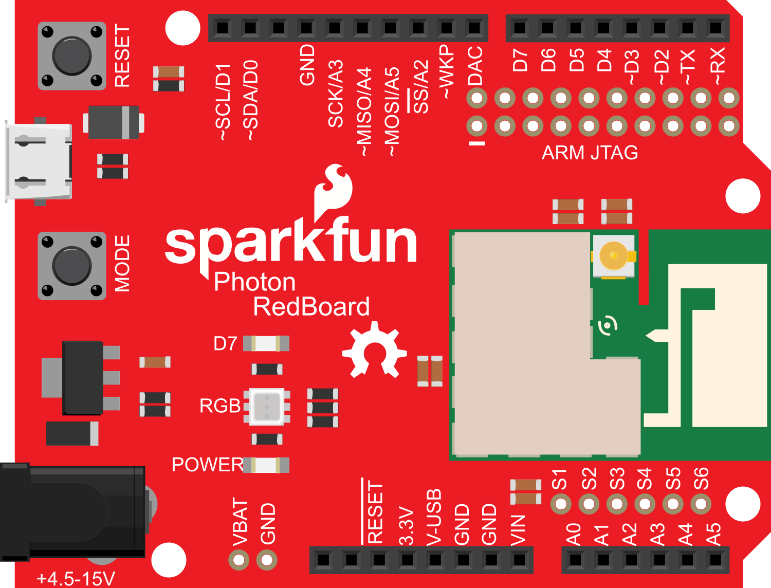
Pin Configuration and Descriptions

Pin Number Function Description
D0-D7 Digital I/O Digital input/output pins, PWM capable
A0-A5 Analog Input Analog input pins, 12-bit ADC
VIN Voltage Input Unregulated input voltage to power the board
3V3 3.3V Output Regulated 3.3V output
GND Ground Ground reference point
RST Reset Resets the microcontroller
TX/RX Serial Comm. Transmit and receive for serial communication
DAC DAC Output Digital-to-Analog Converter output
WKP Wake-up Pin Used to wake up the Photon from sleep mode

Usage Instructions

How to Use the Component in a Circuit

  1. Powering the Board:

    • Connect a power supply to the VIN and GND pins, ensuring the voltage is within the recommended limits.
  2. Connecting to Wi-Fi:

    • Use the Particle app or web IDE to configure the Photon module to connect to your Wi-Fi network.
  3. Interfacing with Sensors/Actuators:

    • Connect sensors to the analog input pins for data acquisition.
    • Connect actuators such as LEDs or motors to the digital I/O pins, considering the current limits.
  4. Programming the Board:

    • The Photon RedBoard can be programmed using the Particle Web IDE, Particle Dev, or the Arduino IDE with the Particle firmware libraries.

Important Considerations and Best Practices

  • Always ensure that the power supply voltage does not exceed the board's limits to prevent damage.
  • When connecting external components, consider the current rating of the I/O pins.
  • Use appropriate decoupling capacitors close to the board's power supply pins to minimize noise.
  • Avoid placing the board in environments with extreme temperatures or humidity.

Example Code for Arduino UNO

// This example demonstrates a simple blink program for the SparkFun Photon RedBoard

// Define the LED pin
int ledPin = D7; // On-board LED

void setup() {
  // Initialize the LED pin as an output
  pinMode(ledPin, OUTPUT);
}

void loop() {
  // Turn the LED on
  digitalWrite(ledPin, HIGH);
  delay(1000); // Wait for 1 second
  // Turn the LED off
  digitalWrite(ledPin, LOW);
  delay(1000); // Wait for 1 second
}

Troubleshooting and FAQs

Common Issues Users Might Face

  • Wi-Fi Connectivity Problems:

    • Ensure the Wi-Fi credentials are entered correctly.
    • Check the signal strength and ensure the Photon is within range of the router.
  • Board Not Powering On:

    • Verify the power supply voltage and connections.
    • Check for any visible signs of damage or short circuits.
  • Inconsistent Behavior or Crashes:

    • Ensure that the firmware is up to date.
    • Check for adequate power supply decoupling.

Solutions and Tips for Troubleshooting

  • Resetting the Board:

    • Use the RST pin to reset the board if it becomes unresponsive.
  • Safe Mode:

    • Enter safe mode to diagnose firmware issues by holding down the SETUP button, then tapping the RESET button.
  • Firmware Updates:

    • Regularly update the firmware through the Particle Web IDE to ensure optimal performance.

FAQs

Q: Can I use the Arduino IDE to program the Photon RedBoard? A: Yes, with the Particle firmware libraries installed, you can use the Arduino IDE.

Q: What is the maximum current the 3V3 pin can supply? A: The 3V3 pin can typically supply up to 100 mA.

Q: How do I connect to the Particle Cloud? A: Use the Particle app or web IDE to configure the Photon module with your Wi-Fi credentials, and it will automatically connect to the Particle Cloud.

Q: Can I use the Photon RedBoard with a battery? A: Yes, you can power the board with a battery, as long as the voltage is within the specified limits.