
How to Use TB6621FNG: Examples, Pinouts, and Specs
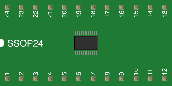
 Design with TB6621FNG in Cirkit Designer
Introduction
The TB6621FNG is a high-performance motor driver IC designed for driving DC motors and stepper motors. It features built-in PWM (Pulse Width Modulation) control for precise motor speed and direction control. Additionally, the IC includes thermal shutdown protection and is capable of handling high current loads, making it a reliable choice for demanding applications. The TB6621FNG is widely used in robotics, automation systems, and other motor control applications.
Explore Projects Built with TB6621FNG
 Open Project in Cirkit Designer
 Open Project in Cirkit Designer
 Open Project in Cirkit Designer
 Open Project in Cirkit Designer
Explore Projects Built with TB6621FNG
Open Project in Cirkit DesignerOpen Project in Cirkit DesignerOpen Project in Cirkit DesignerOpen Project in Cirkit DesignerCommon Applications
- Robotics (e.g., robotic arms, mobile robots)
- Automation systems
- CNC machines
- 3D printers
- Motorized toys and gadgets
Technical Specifications
Key Technical Details
| Parameter | Value |
|---|---|
| Operating Voltage Range | 4.5V to 13.5V |
| Output Current | Up to 1.5A per channel (continuous) |
| Control Method | PWM (Pulse Width Modulation) |
| Motor Types Supported | DC motors, Stepper motors |
| Protection Features | Thermal shutdown, overcurrent protection |
| Package Type | SSOP24 |
Pin Configuration and Descriptions
The TB6621FNG comes in a 24-pin SSOP package. Below is the pin configuration:
| Pin Number | Pin Name | Description |
|---|---|---|
| 1 | VM | Motor power supply input |
| 2 | OUT1A | Output for motor channel 1 (A phase) |
| 3 | OUT1B | Output for motor channel 1 (B phase) |
| 4 | GND | Ground |
| 5 | OUT2A | Output for motor channel 2 (A phase) |
| 6 | OUT2B | Output for motor channel 2 (B phase) |
| 7 | VCC | Logic power supply input |
| 8 | IN1A | Input signal for motor channel 1 (A phase) |
| 9 | IN1B | Input signal for motor channel 1 (B phase) |
| 10 | IN2A | Input signal for motor channel 2 (A phase) |
| 11 | IN2B | Input signal for motor channel 2 (B phase) |
| 12 | ENABLE | Enable pin for motor driver operation |
| 13-24 | NC | No connection (reserved for internal use) |
Usage Instructions
How to Use the TB6621FNG in a Circuit
- Power Supply: Connect the motor power supply to the
VMpin (4.5V to 13.5V) and the logic power supply to theVCCpin (typically 5V). Ensure the ground (GND) is common for both supplies. - Motor Connections: Connect the motor terminals to the output pins (
OUT1A,OUT1B,OUT2A,OUT2B) based on the motor type (DC or stepper motor). - Control Signals: Use the input pins (
IN1A,IN1B,IN2A,IN2B) to control the motor direction and speed via PWM signals. - Enable Pin: Set the
ENABLEpin high to activate the motor driver. Pull it low to disable the outputs. - Protection: Ensure proper heat dissipation and avoid exceeding the current and voltage ratings to prevent damage.
Important Considerations
- Use decoupling capacitors (e.g., 0.1µF and 10µF) near the
VMandVCCpins to stabilize the power supply. - Avoid exceeding the maximum current rating of 1.5A per channel to prevent thermal shutdown.
- For stepper motors, ensure proper sequencing of the input signals to achieve smooth operation.
Example Code for Arduino UNO
Below is an example of how to control a DC motor using the TB6621FNG and an Arduino UNO:
// Define control pins for motor channel 1
const int IN1A = 9;  // PWM pin for motor direction A
const int IN1B = 10; // PWM pin for motor direction B
const int ENABLE = 8; // Enable pin for motor driver

void setup() {
  // Set pin modes
  pinMode(IN1A, OUTPUT);
  pinMode(IN1B, OUTPUT);
  pinMode(ENABLE, OUTPUT);

  // Enable the motor driver
  digitalWrite(ENABLE, HIGH);
}

void loop() {
  // Rotate motor in one direction
  analogWrite(IN1A, 128); // Set speed (0-255)
  analogWrite(IN1B, 0);   // Set opposite direction to 0
  delay(2000);            // Run for 2 seconds

  // Stop the motor
  analogWrite(IN1A, 0);
  analogWrite(IN1B, 0);
  delay(1000);            // Pause for 1 second

  // Rotate motor in the opposite direction
  analogWrite(IN1A, 0);
  analogWrite(IN1B, 128); // Set speed in opposite direction
  delay(2000);            // Run for 2 seconds

  // Stop the motor
  analogWrite(IN1A, 0);
  analogWrite(IN1B, 0);
  delay(1000);            // Pause for 1 second
}
Troubleshooting and FAQs
Common Issues and Solutions
Motor Does Not Spin:
- Ensure the
ENABLEpin is set high. - Verify the power supply connections to
VMandVCC. - Check the input signals (
IN1A,IN1B, etc.) for proper PWM control.
- Ensure the
Motor Spins in the Wrong Direction:
- Swap the input signals (
IN1AandIN1B) or reverse the motor connections.
- Swap the input signals (
Overheating:
- Ensure the current does not exceed 1.5A per channel.
- Use a heatsink or improve ventilation around the IC.
No Output Signal:
- Confirm that the logic power supply (
VCC) is within the specified range. - Check for loose or incorrect wiring.
- Confirm that the logic power supply (
FAQs
Q: Can the TB6621FNG drive two DC motors simultaneously?
A: Yes, the TB6621FNG has two channels and can drive two DC motors independently.
Q: Is the TB6621FNG suitable for high-speed motors?
A: Yes, the built-in PWM control allows for precise speed control, making it suitable for high-speed motors.
Q: Can I use the TB6621FNG with a 3.3V microcontroller?
A: The TB6621FNG requires a logic voltage (VCC) of 5V. Use a level shifter if your microcontroller operates at 3.3V.