How to Use SparkFun BlackBoard Artemis Nano: Examples, Pinouts, and Specs
Introduction
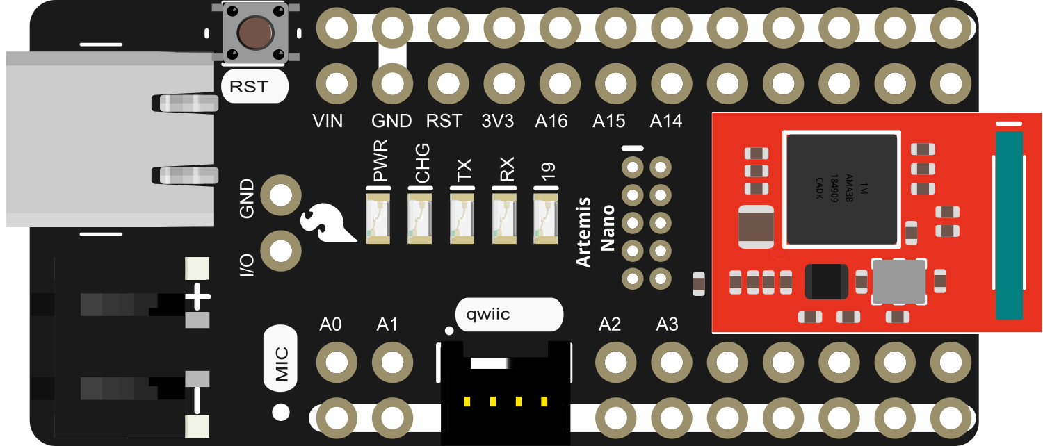
The SparkFun BlackBoard Artemis Nano is a compact, high-performance development board designed around the powerful Ambiq Apollo3 microcontroller. It is part of SparkFun's Artemis family of products, which are aimed at providing a suite of advanced features for a variety of applications, including wearables, gesture recognition, and edge computing. The Artemis Nano is particularly well-suited for projects requiring a small form factor, low power consumption, and wireless connectivity.
Explore Projects Built with SparkFun BlackBoard Artemis Nano

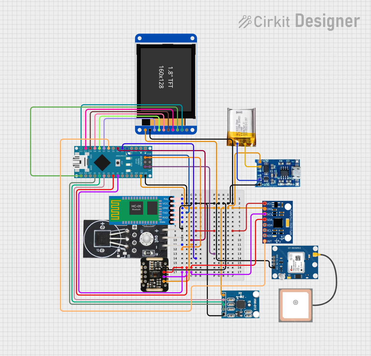
Explore Projects Built with SparkFun BlackBoard Artemis Nano
Common Applications and Use Cases
- Wearable devices
- Fitness and health monitoring systems
- Gesture-controlled gadgets
- Portable instrumentation
- IoT and edge computing devices
- Educational platforms for learning embedded systems and programming
Technical Specifications
Key Technical Details
- Microcontroller: Ambiq Apollo3 ARM Cortex-M4F
- Operating Voltage: 3.3V
- Input Voltage: 5V (via USB-C) or 3.3V to 6V (via Battery)
- Max Current Supply: 1A
- Digital I/O Pins: 11
- Analog Input Pins: 4
- PWM Output: 10
- UARTs: 1
- I2C Buses: 1
- SPI Buses: 1
- Qwiic Connector: Yes
- Flash Memory: 1MB
- SRAM: 384KB
- Clock Speed: 48MHz
- Bluetooth: BLE 5.0
Pin Configuration and Descriptions
| Pin Number | Function | Description |
|---|---|---|
| 1 | GND | Ground |
| 2 | 3.3V | 3.3V power supply |
| 3-5 | Analog Inputs | A0-A2, 14-bit ADC |
| 6-8 | PWM Outputs | PWM capable pins |
| 9 | RX1 | UART receive pin |
| 10 | TX1 | UART transmit pin |
| 11 | I2C SCL | I2C clock line |
| 12 | I2C SDA | I2C data line |
| 13 | SPI SCK | SPI clock line |
| 14 | SPI MISO | SPI Master In Slave Out |
| 15 | SPI MOSI | SPI Master Out Slave In |
| 16 | Qwiic SCL | Qwiic I2C clock line (connected to pin 11) |
| 17 | Qwiic SDA | Qwiic I2C data line (connected to pin 12) |
| 18 | RST | Reset pin |
| 19 | 5V | 5V power supply (USB or VIN) |
| 20 | GND | Ground |
Usage Instructions
How to Use the Component in a Circuit
Powering the Board:
- Connect the USB-C cable to the board and your computer to power the board.
- Alternatively, supply power through the VIN pin (3.3V to 6V).
Connecting Peripherals:
- Use the I2C pins (SCL, SDA) to connect I2C compatible sensors or devices.
- SPI devices can be connected using the SPI pins (SCK, MISO, MOSI).
- PWM outputs can be used to control motors or LEDs.
- Analog inputs can be used to read sensors like potentiometers or temperature sensors.
Programming the Board:
- The board is programmable using the Arduino IDE or other preferred development environments that support the Ambiq Apollo3 microcontroller.
- Select the appropriate board and port in your IDE before uploading your code.
Important Considerations and Best Practices
- Always ensure that the power supply is within the specified range to prevent damage.
- When connecting peripherals, make sure they are compatible with the board's logic level (3.3V).
- Disconnect the board from power sources before making or altering connections.
- Use the onboard Qwiic connector for easy daisy-chaining of I2C devices without soldering.
Example Code for Arduino UNO
// Example Blink Code for SparkFun BlackBoard Artemis Nano

void setup() {
  pinMode(LED_BUILTIN, OUTPUT); // Set the built-in LED pin to be an output
}

void loop() {
  digitalWrite(LED_BUILTIN, HIGH); // Turn the LED on
  delay(1000);                     // Wait for a second
  digitalWrite(LED_BUILTIN, LOW);  // Turn the LED off
  delay(1000);                     // Wait for a second
}
Troubleshooting and FAQs
Common Issues
Board not recognized by the computer:
- Ensure the USB cable is properly connected and the computer's USB port is functioning.
- Try a different USB cable or port to rule out hardware issues.
Unable to upload code:
- Check that the correct board and port are selected in the IDE.
- Ensure the board's drivers are installed correctly.
Peripherals not working:
- Verify that all connections are secure and correct.
- Ensure that the peripheral is compatible with the board's logic level.
Solutions and Tips for Troubleshooting
- If the board is not recognized, press and hold the reset button for a few seconds to reset the board.
- When encountering issues with uploading code, check the IDE's console for error messages that can provide clues.
- For peripheral issues, consult the datasheet of the peripheral to ensure proper usage and compatibility.
FAQs
Q: Can the Artemis Nano be used with a battery? A: Yes, it can be powered with a battery connected to the VIN pin.
Q: Is the Artemis Nano compatible with all Arduino libraries? A: While many libraries will work, some may need modifications due to differences in hardware.
Q: How do I use Bluetooth functionality? A: Bluetooth functionality can be accessed through the Ambiq Apollo3 SDK or libraries specifically designed for the Artemis module.
Q: What is the maximum voltage that can be applied to the analog inputs? A: The maximum voltage for the analog inputs is 3.3V. Applying more can damage the board.