How to Use Switch 32 mm Black: Examples, Pinouts, and Specs
Introduction
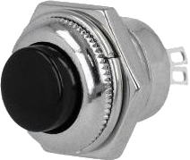
The Black Momentary Switch 32 mm is a mechanical device designed to control the flow of electricity within a circuit. It operates by making or breaking the electrical connection when the button is pressed, allowing current to flow only while the switch is actuated. This type of switch is commonly used in applications where user input is required to momentarily activate or deactivate a device, such as in electronic keyboards, push-button telephones, and as a reset or control button on various electronic devices.
Explore Projects Built with Switch 32 mm Black
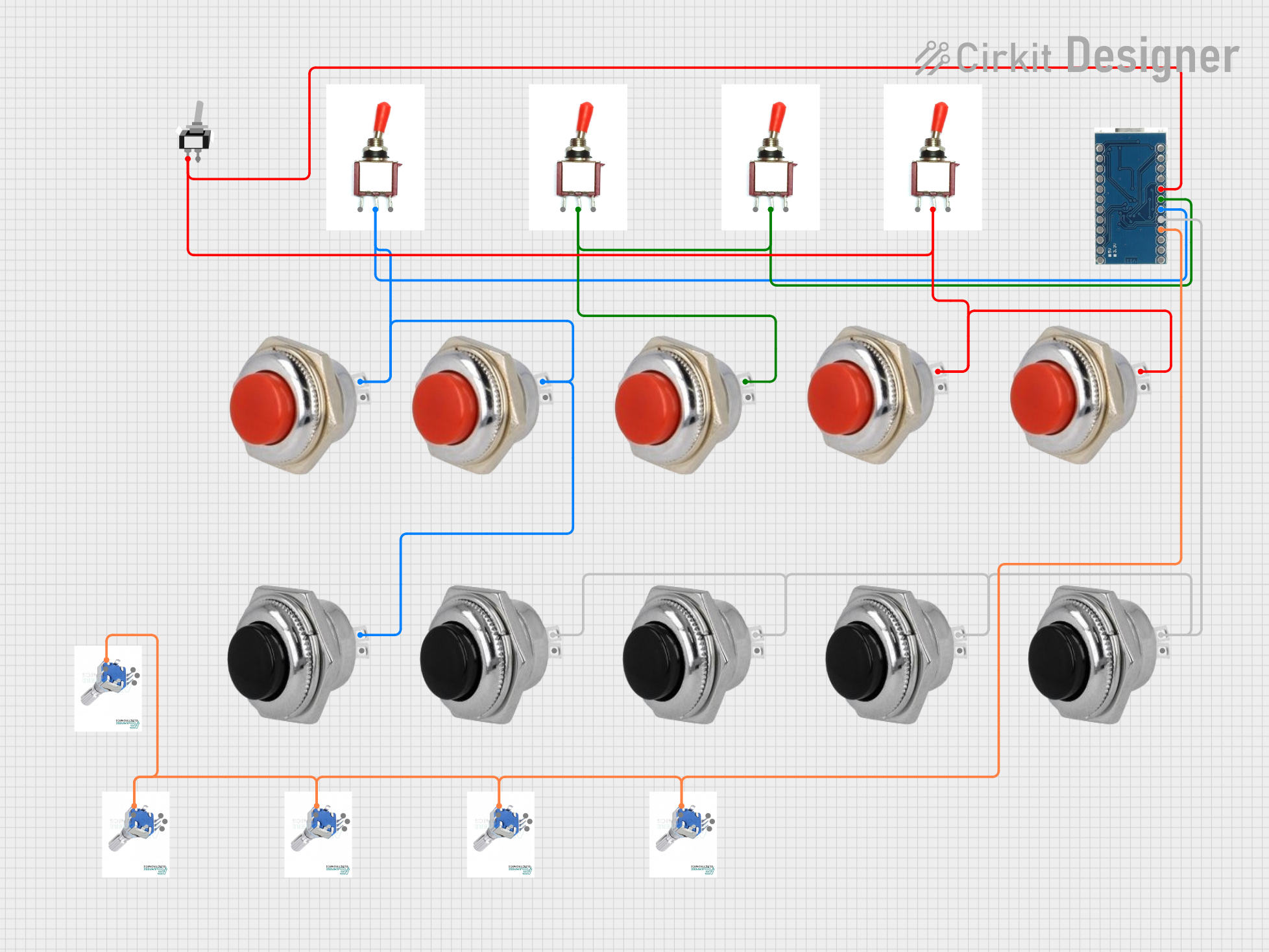

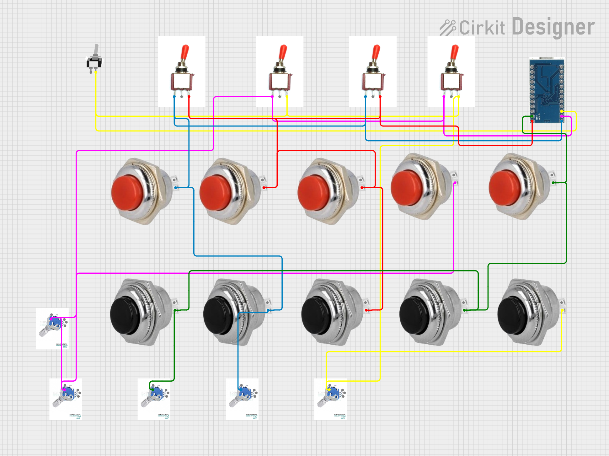
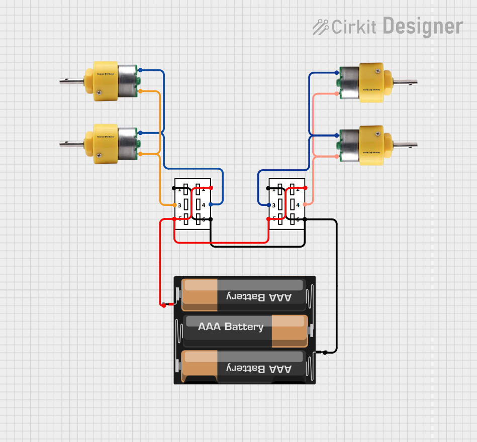
Explore Projects Built with Switch 32 mm Black
Common Applications and Use Cases
- As a reset switch in electronic circuits
- For user input in interactive installations
- In control panels for machinery
- On handheld devices for temporary activation or deactivation
- In DIY projects and prototypes, often interfaced with microcontrollers like Arduino
Technical Specifications
Key Technical Details
- Switch Type: Momentary
- Actuator Color: Black
- Mounting Hole Size: 32 mm diameter
- Contact Rating: Typically 1-5 A at 250V AC or 30V DC
- Contact Resistance: < 50 mΩ initial
- Insulation Resistance: > 1000 MΩ at 500V DC
- Dielectric Strength: > 2000V AC for 1 minute
- Operating Temperature Range: -20°C to +70°C
- Mechanical Life: > 1,000,000 cycles
- Electrical Life: > 50,000 cycles
Pin Configuration and Descriptions
| Pin Number | Description |
|---|---|
| 1 | Normally Open (NO) |
| 2 | Common (COM) |
| 3 | Normally Closed (NC) |
Usage Instructions
How to Use the Component in a Circuit
- Mounting: Secure the switch in a 32 mm diameter hole on your panel or enclosure.
- Wiring:
- Connect the COM pin to one side of the power source.
- Connect the NO pin to the load (e.g., LED, relay, or other devices).
- The NC pin is optional and can be used if a normally closed operation is required.
- Operation: Press the switch to momentarily close the circuit between the COM and NO pins. Release the switch to open the circuit.
Important Considerations and Best Practices
- Ensure the switch's ratings match or exceed the requirements of your application.
- Use a pull-down or pull-up resistor if interfacing with a microcontroller to ensure a stable signal.
- Avoid excessive force to prevent mechanical damage.
- Keep the switch clean and free from dust for reliable operation.
Example Code for Arduino UNO
// Define the pin connected to the switch
const int switchPin = 2;

void setup() {
  // Set the switch pin as input with an internal pull-up resistor
  pinMode(switchPin, INPUT_PULLUP);
  // Initialize serial communication for debugging
  Serial.begin(9600);
}

void loop() {
  // Read the state of the switch
  int switchState = digitalRead(switchPin);

  // Check if the switch is pressed (LOW when pressed due to pull-up resistor)
  if (switchState == LOW) {
    // Perform an action, e.g., turn on an LED, send a signal, etc.
    Serial.println("Switch Pressed");
    // Debounce delay to avoid detecting multiple presses from one press
    delay(50);
  }
}
Troubleshooting and FAQs
Common Issues Users Might Face
- Switch does not respond: Ensure all connections are secure and the switch is not damaged.
- Intermittent operation: Check for loose connections or solder joints.
- Switch feels stuck: Debris or mechanical wear may be the cause; inspect and clean or replace if necessary.
Solutions and Tips for Troubleshooting
- Verify that the switch is properly mounted and that pins are not bent or broken.
- Test the switch with a multimeter to ensure it is functioning correctly.
- If using with a microcontroller, ensure that the input pin is configured correctly and that the pull-up or pull-down resistor is in place.
FAQs
Q: Can I use this switch with a higher voltage or current? A: No, exceeding the specified voltage or current ratings can be dangerous and may damage the switch.
Q: Is the switch waterproof? A: Typically, momentary switches like this are not waterproof unless specified by the manufacturer.
Q: How do I know if the switch is in a normally open or normally closed state? A: When unpressed, the switch is in a normally open state, meaning the circuit is open and no current flows. When pressed, it momentarily closes the circuit, allowing current to flow.
Q: Can I use this switch with an AC load? A: Yes, as long as the load does not exceed the switch's AC rating.
Remember to always follow safety guidelines when working with electronic components and consult an expert if you are unsure about your application.