How to Use 12V 15A Power Supply: Examples, Pinouts, and Specs
12V 15A Power Supply Documentation
Introduction
The 12V 15A Power Supply (Manufacturer: AC, Part ID: Power Supply) is a robust and reliable device designed to convert AC mains voltage into a stable 12V DC output. With a maximum current capacity of 15A, this power supply is ideal for powering a wide range of electronic devices, including LED strips, motors, microcontrollers, and other high-current applications. Its compact design and high efficiency make it a popular choice for both hobbyists and professionals.
Common Applications
- Powering LED lighting systems (e.g., LED strips, LED panels)
- Supplying power to microcontroller-based projects (e.g., Arduino, Raspberry Pi)
- Driving DC motors in robotics and automation systems
- Providing power for CCTV cameras and security systems
- General-purpose DC power supply for laboratory and prototyping use
Technical Specifications
The following table outlines the key technical details of the 12V 15A Power Supply:
| Parameter | Specification |
|---|---|
| Input Voltage | 100-240V AC, 50/60Hz |
| Output Voltage | 12V DC |
| Maximum Output Current | 15A |
| Maximum Output Power | 180W |
| Efficiency | ≥85% |
| Operating Temperature | -10°C to +50°C |
| Dimensions | Varies by model (e.g., 200mm x 100mm x 50mm) |
| Weight | ~500g to 1kg (depending on model) |
| Protection Features | Overload, Overvoltage, Short Circuit |
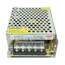
Pin Configuration and Descriptions
The power supply typically has the following input and output terminals:
| Terminal | Label | Description |
|---|---|---|
| Input 1 | L | Live wire (AC mains input) |
| Input 2 | N | Neutral wire (AC mains input) |
| Input 3 | GND | Ground wire (optional, for safety) |
| Output 1 | +V | Positive DC output (12V) |
| Output 2 | -V | Negative DC output (Ground) |
| Adjustment | V-ADJ | Voltage adjustment potentiometer (±10% adjustment) |
Usage Instructions
Connecting the Power Supply
- Safety First: Ensure the power supply is disconnected from the mains before making any connections.
- Input Connection:
- Connect the L terminal to the live wire of the AC mains.
- Connect the N terminal to the neutral wire of the AC mains.
- Optionally, connect the GND terminal to the ground wire for safety.
- Output Connection:
- Connect the +V terminal to the positive input of your load or circuit.
- Connect the -V terminal to the ground or negative input of your load or circuit.
- Voltage Adjustment:
- Use the V-ADJ potentiometer to fine-tune the output voltage if necessary (±10% adjustment range).
Important Considerations
- Load Capacity: Ensure the total current drawn by the connected devices does not exceed 15A.
- Ventilation: Place the power supply in a well-ventilated area to prevent overheating.
- Polarity: Double-check the polarity of the output connections to avoid damaging your devices.
- Fusing: Use an appropriate fuse on the input side for added protection.
Example: Powering an Arduino UNO
To power an Arduino UNO using the 12V 15A power supply:
- Connect the +V terminal to the Arduino's VIN pin.
- Connect the -V terminal to the Arduino's GND pin.
- Ensure the Arduino's onboard voltage regulator is functioning properly to step down the 12V to 5V.
Troubleshooting and FAQs
Common Issues and Solutions
| Issue | Possible Cause | Solution |
|---|---|---|
| No output voltage | Input AC power not connected | Verify the AC mains connection. |
| Blown fuse inside the power supply | Replace the fuse with the correct rating. | |
| Output voltage too high/low | Voltage adjustment potentiometer misaligned | Adjust the V-ADJ potentiometer. |
| Power supply overheats | Insufficient ventilation | Ensure proper airflow around the power supply. |
| Load exceeds maximum current rating | Reduce the load to within 15A. | |
| Device connected to output not working | Incorrect polarity or loose connections | Verify and correct the output connections. |
FAQs
Can I use this power supply to charge a 12V battery?
- Yes, but ensure the battery charging current does not exceed 15A. Use a charge controller for optimal performance and safety.
Is the power supply waterproof?
- No, this power supply is not waterproof. Use it in a dry environment or enclose it in a waterproof housing if necessary.
Can I adjust the output voltage?
- Yes, the output voltage can be adjusted within ±10% of 12V using the V-ADJ potentiometer.
What happens if the load exceeds 15A?
- The power supply's overload protection will activate, shutting down the output to prevent damage.
Example Arduino Code
Below is an example of using the 12V 15A power supply to power an Arduino UNO and control an LED:
// Example: Controlling an LED with Arduino powered by 12V 15A Power Supply

// Define the LED pin
const int ledPin = 13; // Onboard LED pin on Arduino UNO

void setup() {
  pinMode(ledPin, OUTPUT); // Set the LED pin as an output
}

void loop() {
  digitalWrite(ledPin, HIGH); // Turn the LED on
  delay(1000);                // Wait for 1 second
  digitalWrite(ledPin, LOW);  // Turn the LED off
  delay(1000);                // Wait for 1 second
}
Note: Connect the power supply's +V to the Arduino's VIN pin and -V to the GND pin. Ensure the Arduino's onboard voltage regulator is functioning properly to step down the 12V to 5V.
Conclusion
The 12V 15A Power Supply is a versatile and reliable component for powering a wide range of electronic devices and circuits. By following the usage instructions and best practices outlined in this documentation, you can ensure safe and efficient operation. Whether you're a hobbyist or a professional, this power supply is an essential tool for your projects.
Explore Projects Built with 12V 15A Power Supply


Explore Projects Built with 12V 15A Power Supply