How to Use HW-434 with DRV8825: Examples, Pinouts, and Specs
Introduction
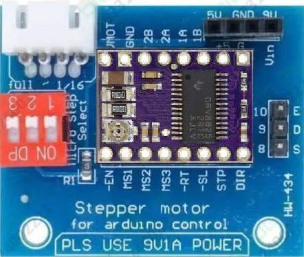
The HW-434 is a stepper motor driver module built around the DRV8825 chip, designed for precise control of stepper motors. It supports microstepping, which allows for smoother operation and higher resolution in motor movements. This module is widely used in applications such as robotics, 3D printers, CNC machines, and other systems requiring accurate motor control.
The HW-434 is compatible with a wide range of stepper motors and can handle high current loads, making it a versatile and reliable choice for both hobbyists and professionals.
Explore Projects Built with HW-434 with DRV8825
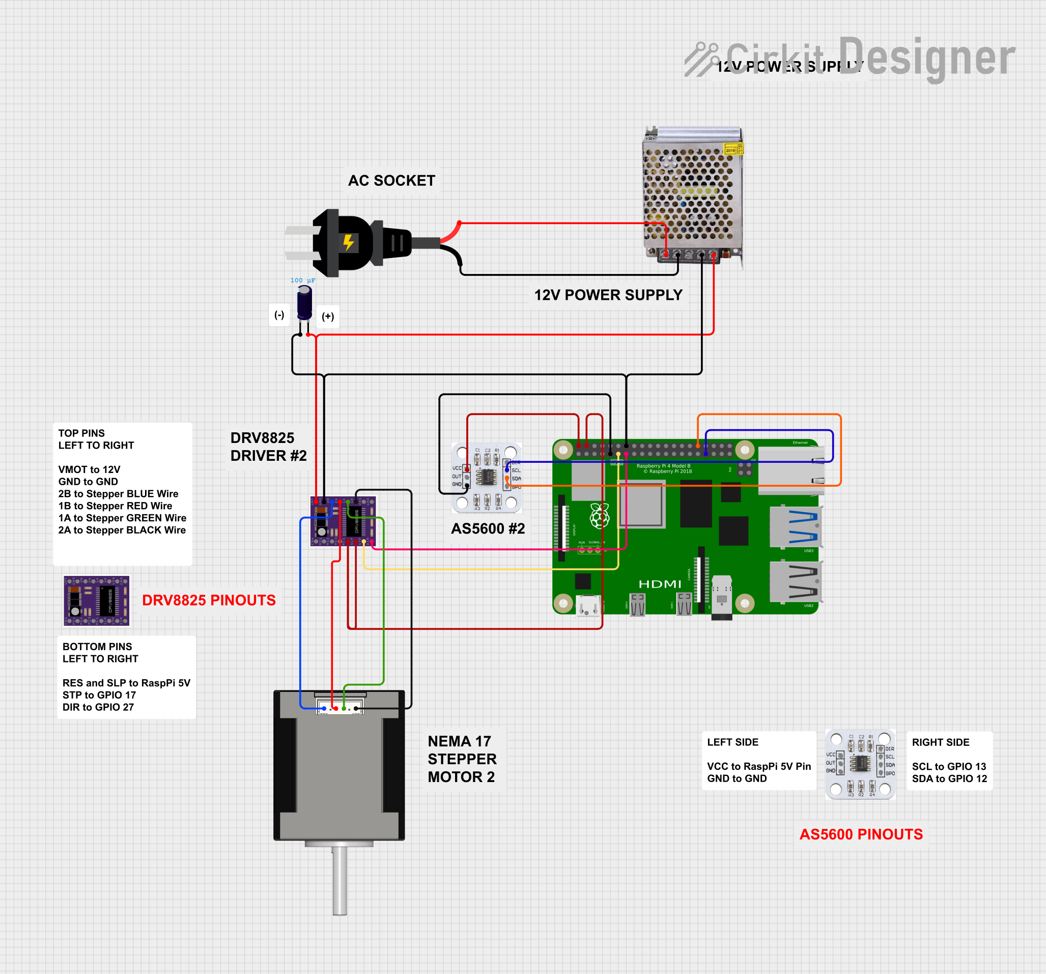
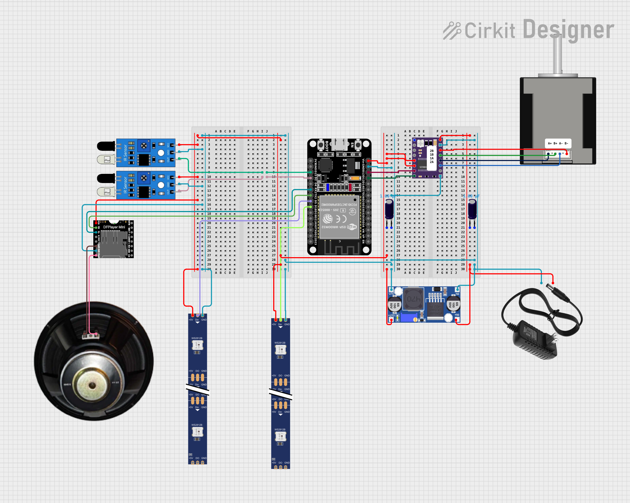
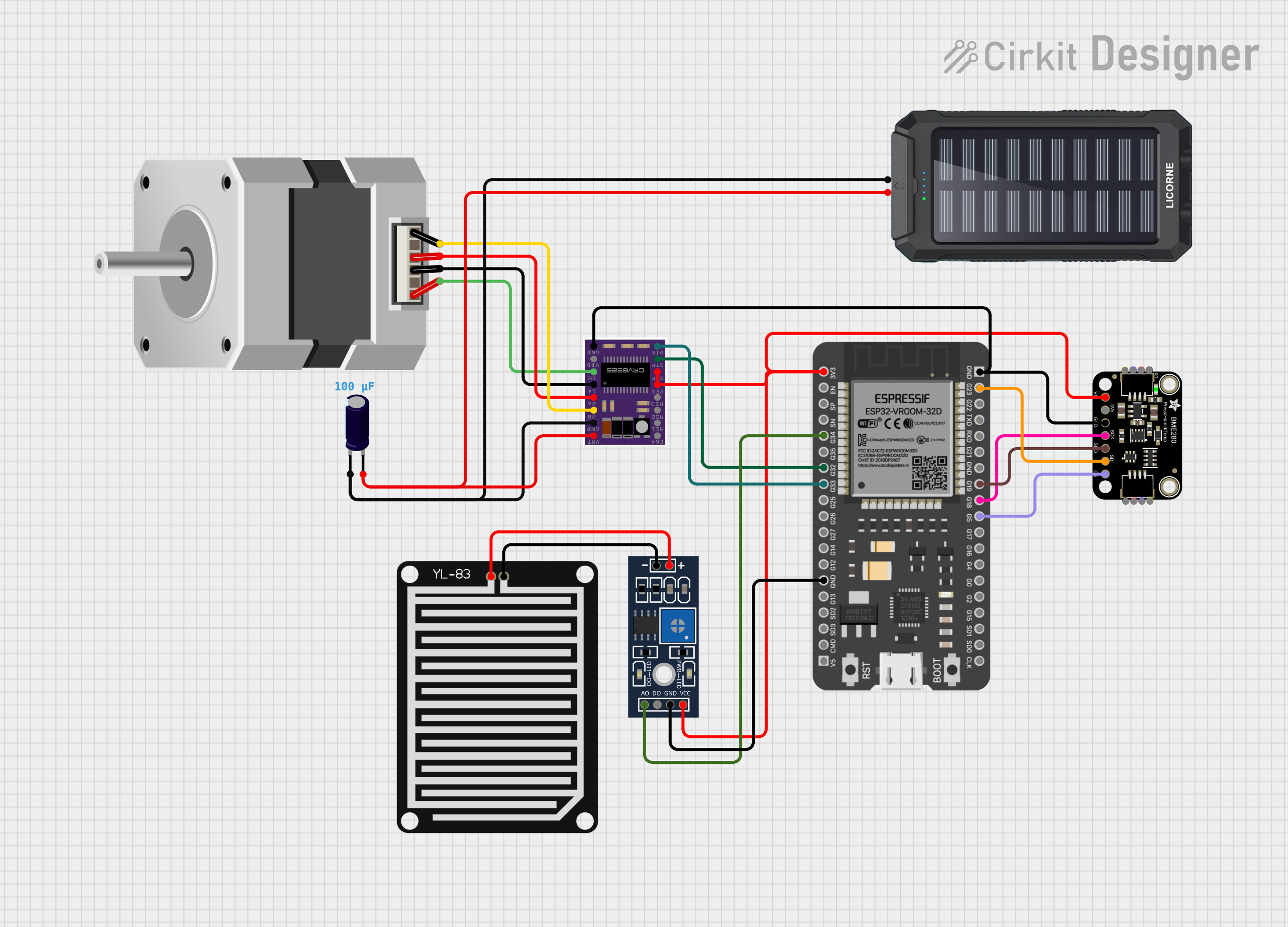
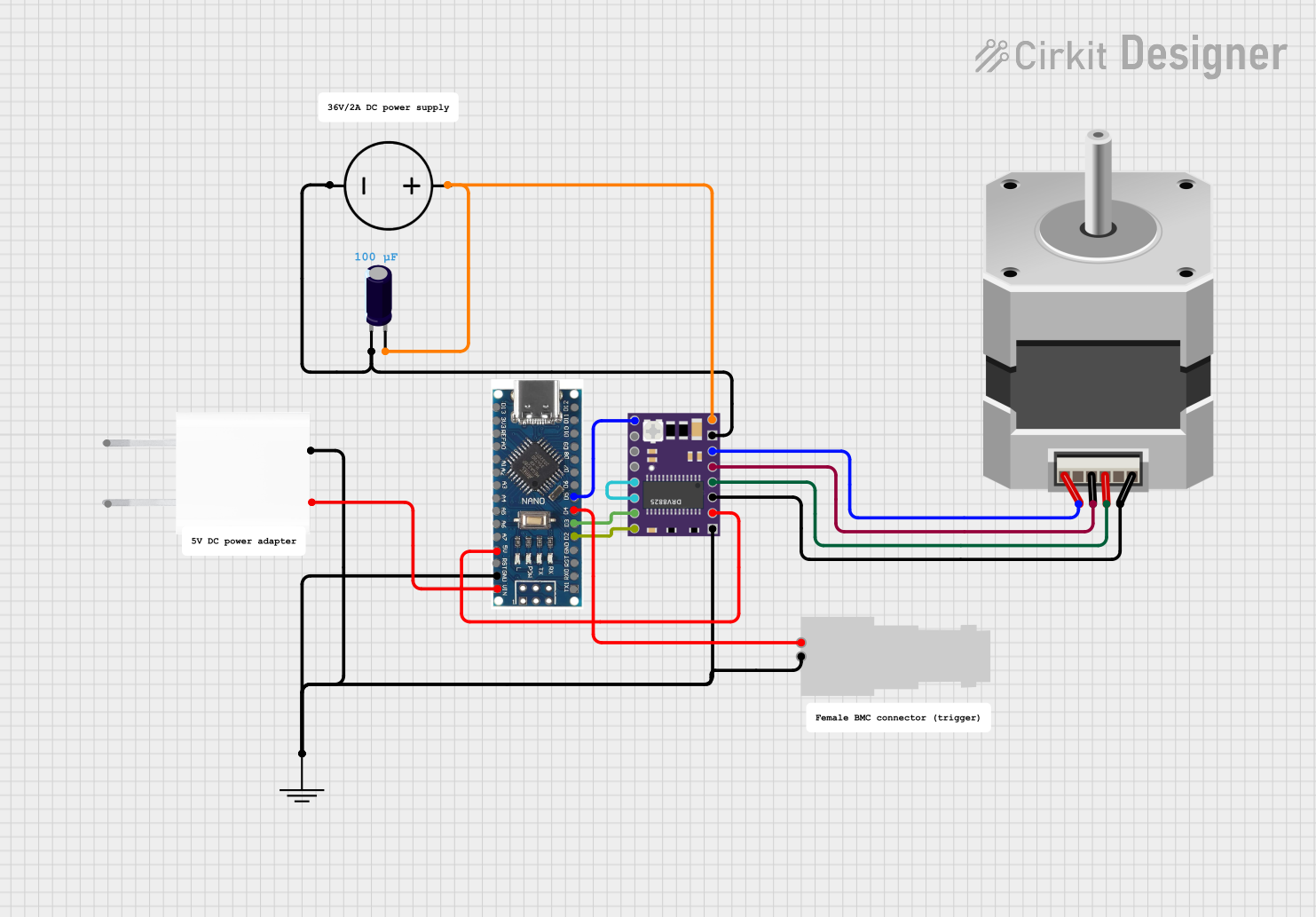
Explore Projects Built with HW-434 with DRV8825
Technical Specifications
Key Technical Details
- Driver Chip: DRV8825
- Input Voltage: 8.2V to 45V DC
- Output Current: Up to 2.5A per coil (with sufficient cooling)
- Microstepping: Full-step, 1/2, 1/4, 1/8, 1/16, and 1/32 steps
- Logic Voltage: 3.3V or 5V compatible
- Thermal Shutdown: Built-in over-temperature protection
- Overcurrent Protection: Yes
- Dimensions: 15mm x 20mm (approx.)
Pin Configuration and Descriptions
The HW-434 module has 16 pins. Below is the pinout and description:
| Pin Name | Type | Description |
|---|---|---|
| VMOT | Power Input | Motor power supply (8.2V to 45V DC). Connect to the stepper motor power source. |
| GND | Power Ground | Ground connection for motor power supply. |
| 2B, 2A | Motor Output | Connect to one coil of the stepper motor. |
| 1A, 1B | Motor Output | Connect to the other coil of the stepper motor. |
| VDD | Power Input | Logic voltage input (3.3V or 5V). |
| GND | Power Ground | Ground connection for logic voltage. |
| STEP | Logic Input | Step signal input. Each pulse moves the motor one step. |
| DIR | Logic Input | Direction control input. High or low determines motor rotation direction. |
| ENABLE | Logic Input | Enable/disable the driver. Low to enable, high to disable. |
| MS1, MS2, MS3 | Logic Inputs | Microstepping resolution selection. |
| RESET | Logic Input | Resets the driver. Active low. |
| SLEEP | Logic Input | Puts the driver into low-power sleep mode. Active low. |
Microstepping Configuration
The microstepping resolution is set using the MS1, MS2, and MS3 pins. The table below shows the configuration:
| MS1 | MS2 | MS3 | Microstepping Mode |
|---|---|---|---|
| Low | Low | Low | Full Step |
| High | Low | Low | 1/2 Step |
| Low | High | Low | 1/4 Step |
| High | High | Low | 1/8 Step |
| Low | Low | High | 1/16 Step |
| High | High | High | 1/32 Step |
Usage Instructions
How to Use the HW-434 in a Circuit
Power Connections:
- Connect the VMOT pin to the motor power supply (8.2V to 45V DC).
- Connect the GND pin to the ground of the motor power supply.
- Connect the VDD pin to the logic voltage (3.3V or 5V).
- Connect the logic GND pin to the ground of the logic circuit.
Motor Connections:
- Connect the stepper motor coils to the 1A, 1B, 2A, and 2B pins. Ensure the correct pairing of the motor wires.
Control Signals:
- Connect the STEP pin to a microcontroller or pulse generator to control the steps.
- Connect the DIR pin to set the motor's rotation direction.
- Use the ENABLE pin to enable or disable the driver.
Microstepping:
- Set the MS1, MS2, and MS3 pins to configure the desired microstepping mode.
Adjusting Current Limit:
- Use the onboard potentiometer to adjust the current limit. This prevents overheating and ensures safe operation of the motor.
Important Considerations and Best Practices
- Cooling: The DRV8825 chip can get hot during operation. Use a heatsink or active cooling for high-current applications.
- Current Limit: Always set the current limit to match your stepper motor's rated current to avoid damage.
- Decoupling Capacitors: Add a 100µF electrolytic capacitor across VMOT and GND to reduce voltage spikes.
- Sleep Mode: Use the SLEEP pin to reduce power consumption when the driver is not in use.
Example: Connecting to an Arduino UNO
Below is an example of how to control the HW-434 with an Arduino UNO:
// Define pin connections
#define STEP_PIN 3  // Connect to STEP pin on HW-434
#define DIR_PIN 4   // Connect to DIR pin on HW-434
#define ENABLE_PIN 5 // Connect to ENABLE pin on HW-434

void setup() {
  pinMode(STEP_PIN, OUTPUT);  // Set STEP pin as output
  pinMode(DIR_PIN, OUTPUT);   // Set DIR pin as output
  pinMode(ENABLE_PIN, OUTPUT); // Set ENABLE pin as output

  digitalWrite(ENABLE_PIN, LOW); // Enable the driver
  digitalWrite(DIR_PIN, HIGH);   // Set direction (HIGH or LOW)
}

void loop() {
  // Generate step pulses
  digitalWrite(STEP_PIN, HIGH);  // Step pulse HIGH
  delayMicroseconds(500);        // Wait 500 microseconds
  digitalWrite(STEP_PIN, LOW);   // Step pulse LOW
  delayMicroseconds(500);        // Wait 500 microseconds
}
Troubleshooting and FAQs
Common Issues and Solutions
Motor Not Moving:
- Check all power and motor connections.
- Ensure the STEP pin is receiving pulses from the microcontroller.
- Verify the current limit is set correctly.
Overheating:
- Ensure proper cooling (e.g., heatsink or fan).
- Check that the current limit is not set too high.
Erratic Motor Movement:
- Verify the microstepping configuration (MS1, MS2, MS3 pins).
- Check for loose or incorrect motor connections.
Driver Not Responding:
- Ensure the ENABLE pin is set to LOW.
- Check the logic voltage (VDD) and ground connections.
FAQs
Can I use the HW-434 with a 12V power supply? Yes, the module supports input voltages from 8.2V to 45V DC.
What happens if I exceed the current limit? The DRV8825 has built-in overcurrent protection, but exceeding the limit can cause overheating or damage. Always set the current limit appropriately.
Can I use this module with a 6-wire stepper motor? Yes, but you need to identify and connect the correct coil pairs. Leave the center taps unconnected.
Is the HW-434 compatible with 3.3V logic? Yes, the module is compatible with both 3.3V and 5V logic levels.