How to Use lora booster: Examples, Pinouts, and Specs
Introduction
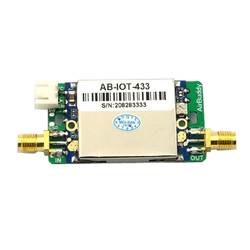
A LoRa booster is a device designed to amplify the signal strength of LoRa (Long Range) radio communications. LoRa technology is widely used in IoT (Internet of Things) applications due to its ability to transmit data over long distances with low power consumption. By enhancing the signal strength, a LoRa booster improves the range, reliability, and overall performance of wireless data transmission, making it ideal for applications in remote monitoring, smart agriculture, industrial automation, and smart cities.
Explore Projects Built with lora booster

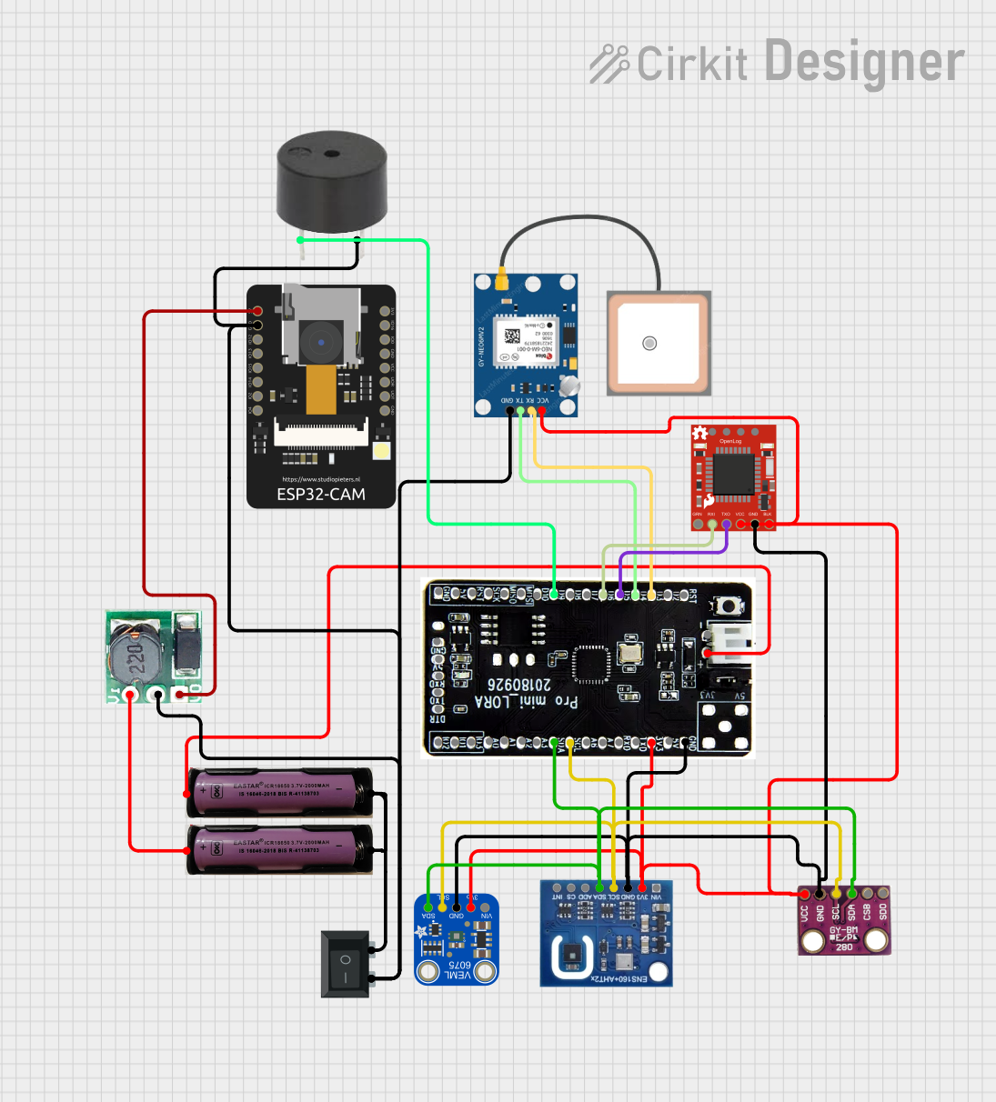

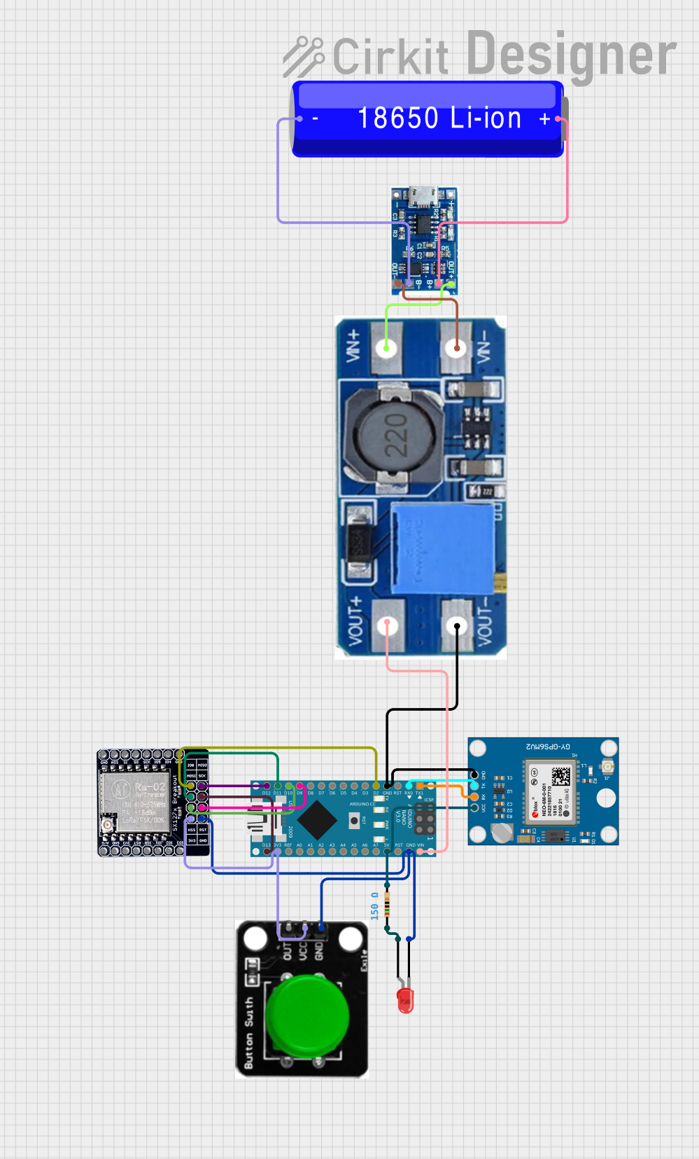
Explore Projects Built with lora booster
Common Applications and Use Cases
- Extending the range of LoRa-based IoT networks in rural or urban environments.
- Improving signal reliability in areas with high interference or obstacles.
- Enhancing communication for smart agriculture systems, such as soil sensors and weather stations.
- Supporting industrial IoT applications, including asset tracking and predictive maintenance.
- Boosting connectivity in smart city applications, such as parking sensors and environmental monitoring.
Technical Specifications
Below are the key technical details of a typical LoRa booster:
| Parameter | Value |
|---|---|
| Operating Voltage | 3.3V to 5V |
| Operating Current | 100mA to 200mA (depending on power level) |
| Frequency Range | 433 MHz / 868 MHz / 915 MHz |
| Output Power | Up to +20 dBm |
| Input Signal Sensitivity | -140 dBm |
| Amplification Gain | 20 dB to 30 dB |
| Operating Temperature | -40°C to +85°C |
| Communication Interface | SMA connector for RF input/output |
Pin Configuration and Descriptions
The LoRa booster typically has the following pin configuration:
| Pin Name | Description |
|---|---|
| VCC | Power supply input (3.3V to 5V) |
| GND | Ground connection |
| RF_IN | RF signal input from the LoRa module |
| RF_OUT | Amplified RF signal output to the antenna |
| EN | Enable pin to turn the booster on/off |
Usage Instructions
How to Use the LoRa Booster in a Circuit
- Power Supply: Connect the VCC pin to a 3.3V or 5V power source and the GND pin to the ground of your circuit.
- Signal Input: Connect the RF_IN pin to the RF output of your LoRa module.
- Signal Output: Connect the RF_OUT pin to an external antenna using an SMA connector.
- Enable Pin: If the booster has an EN pin, ensure it is pulled high to enable the booster. You can connect it to VCC or control it via a microcontroller GPIO pin.
- Antenna Placement: Place the antenna in a location with minimal obstructions to maximize signal range.
Important Considerations and Best Practices
- Power Supply: Ensure the power supply can provide sufficient current (up to 200mA) for the booster to operate effectively.
- Heat Dissipation: The booster may generate heat during operation. Use proper ventilation or a heatsink if necessary.
- Frequency Matching: Use an antenna that matches the frequency range of your LoRa module (e.g., 433 MHz, 868 MHz, or 915 MHz).
- Regulatory Compliance: Ensure your setup complies with local regulations for RF transmission power and frequency usage.
- Signal Interference: Avoid placing the booster near sources of electromagnetic interference, such as motors or high-frequency circuits.
Example: Connecting a LoRa Booster to an Arduino UNO
Below is an example of how to connect a LoRa booster to an Arduino UNO and control the EN pin:
Circuit Connections
- Connect the VCC pin of the booster to the 5V pin of the Arduino.
- Connect the GND pin of the booster to the GND pin of the Arduino.
- Connect the RF_IN pin of the booster to the RF output of the LoRa module.
- Connect the RF_OUT pin of the booster to the antenna.
- Connect the EN pin of the booster to a digital pin on the Arduino (e.g., pin 7).
Arduino Code Example
// Define the EN pin for the LoRa booster
const int boosterEnablePin = 7;

void setup() {
  // Initialize the EN pin as an output
  pinMode(boosterEnablePin, OUTPUT);

  // Enable the LoRa booster
  digitalWrite(boosterEnablePin, HIGH);

  // Optional: Add a delay to ensure the booster is fully powered
  delay(100);
}

void loop() {
  // Your main code for LoRa communication goes here

  // Example: Toggle the booster off and on (if needed)
  digitalWrite(boosterEnablePin, LOW);  // Turn off the booster
  delay(1000);                          // Wait for 1 second
  digitalWrite(boosterEnablePin, HIGH); // Turn on the booster
  delay(1000);                          // Wait for 1 second
}
Troubleshooting and FAQs
Common Issues and Solutions
No Signal Amplification:
- Cause: Incorrect wiring or insufficient power supply.
- Solution: Double-check all connections and ensure the power supply meets the current requirements.
Overheating:
- Cause: Prolonged operation at maximum power without proper cooling.
- Solution: Add a heatsink or improve ventilation around the booster.
Intermittent Signal Loss:
- Cause: Poor antenna placement or interference.
- Solution: Reposition the antenna to a higher or less obstructed location. Avoid placing the booster near sources of interference.
Low Output Power:
- Cause: Mismatched antenna or incorrect frequency settings.
- Solution: Use an antenna that matches the frequency range of your LoRa module and booster.
FAQs
Q: Can I use the LoRa booster with any LoRa module?
A: Yes, as long as the module operates within the supported frequency range and the RF output is compatible with the booster.
Q: Is the LoRa booster compatible with battery-powered systems?
A: Yes, but ensure the battery can provide sufficient current for the booster to operate effectively.
Q: How far can the LoRa booster extend the range?
A: The range extension depends on factors such as antenna quality, environmental conditions, and regulatory power limits. In ideal conditions, it can extend the range by several kilometers.
Q: Do I need to enable the booster manually?
A: If the booster has an EN pin, you can control it manually or via a microcontroller. Some boosters may not have an EN pin and are always active when powered.