Cirkit Designer Logo
Cirkit Designer
Your all-in-one circuit design IDE
Home / 
Component Documentation

How to Use Arduino Micro (Rev3): Examples, Pinouts, and Specs

Image of Arduino Micro (Rev3)
Cirkit Designer LogoDesign with Arduino Micro (Rev3) in Cirkit Designer

Introduction

The Arduino Micro (Rev3) is a compact microcontroller board based on the ATmega32U4. It is a member of the Arduino family and is notable for its small size, making it ideal for embedding into projects where space is at a premium. The board comes with built-in USB communication, eliminating the need for a secondary processor. This feature allows the Arduino Micro to appear as a mouse or keyboard, in addition to a virtual (CDC) serial / COM port. It is commonly used in prototyping, DIY electronics, educational projects, and interactive artworks.

Explore Projects Built with Arduino Micro (Rev3)

Use Cirkit Designer to design, explore, and prototype these projects online. Some projects support real-time simulation. Click "Open Project" to start designing instantly!
Arduino Uno R3-Based Voice-Controlled Robot with Servo Actuation and SD Logging
Image of wheel: A project utilizing Arduino Micro (Rev3) in a practical application
This circuit features an Arduino Uno R3 as the central microcontroller, interfaced with a variety of components. It includes a voice recognition module for audio input commands, an analog thumbstick for manual control, and multiple servos for actuation. Additionally, the circuit integrates an I2C LCD screen for display purposes, an infrared proximity sensor for distance measurement, and a micro SD card module for data storage.
Cirkit Designer LogoOpen Project in Cirkit Designer
ATmega328P-Based Sensor Hub with OLED Display and LIDAR
Image of TILTPCB: A project utilizing Arduino Micro (Rev3) in a practical application
This circuit features an Mtiny Uno ATmega328P microcontroller as its central processing unit, interfacing with a variety of sensors and peripherals. It includes a 0.96" OLED display and an MPU6050 accelerometer/gyroscope for user interface and motion sensing, respectively. The circuit also integrates a TF LUNA LIDAR for distance measurement, a DHT11 sensor for temperature and humidity readings, and uses a 9V battery with a 7805 voltage regulator for power management. Communication with a computer for programming and data exchange is facilitated by an Adafruit FTDI Friend module.
Cirkit Designer LogoOpen Project in Cirkit Designer
Arduino Leonardo-Controlled Robot with L298N Motor Driver and Multiple Sensors
Image of arduino car: A project utilizing Arduino Micro (Rev3) in a practical application
This is a microcontroller-based control system using an Arduino Leonardo to manage DC gearmotors through an L298N motor driver, process inputs from IR and ultrasonic sensors, and actuate a servomotor. It features visual indicators (LEDs), an audible alert (piezo speaker), and a power management system with a rocker switch.
Cirkit Designer LogoOpen Project in Cirkit Designer
Arduino-Based GPS Speedometer with LCD Display and Relay Control
Image of Speedometer Praktis: A project utilizing Arduino Micro (Rev3) in a practical application
This circuit integrates an Arduino Micro with various sensors (GPS, MPU-6050, light, sound) and a 20x4 LCD display to monitor environmental data and display it. The Arduino controls a relay based on a push button input and displays GPS speed data on the LCD, while also reading sensor data for potential further processing.
Cirkit Designer LogoOpen Project in Cirkit Designer

Explore Projects Built with Arduino Micro (Rev3)

Use Cirkit Designer to design, explore, and prototype these projects online. Some projects support real-time simulation. Click "Open Project" to start designing instantly!
Image of wheel: A project utilizing Arduino Micro (Rev3) in a practical application
Arduino Uno R3-Based Voice-Controlled Robot with Servo Actuation and SD Logging
This circuit features an Arduino Uno R3 as the central microcontroller, interfaced with a variety of components. It includes a voice recognition module for audio input commands, an analog thumbstick for manual control, and multiple servos for actuation. Additionally, the circuit integrates an I2C LCD screen for display purposes, an infrared proximity sensor for distance measurement, and a micro SD card module for data storage.
Cirkit Designer LogoOpen Project in Cirkit Designer
Image of TILTPCB: A project utilizing Arduino Micro (Rev3) in a practical application
ATmega328P-Based Sensor Hub with OLED Display and LIDAR
This circuit features an Mtiny Uno ATmega328P microcontroller as its central processing unit, interfacing with a variety of sensors and peripherals. It includes a 0.96" OLED display and an MPU6050 accelerometer/gyroscope for user interface and motion sensing, respectively. The circuit also integrates a TF LUNA LIDAR for distance measurement, a DHT11 sensor for temperature and humidity readings, and uses a 9V battery with a 7805 voltage regulator for power management. Communication with a computer for programming and data exchange is facilitated by an Adafruit FTDI Friend module.
Cirkit Designer LogoOpen Project in Cirkit Designer
Image of arduino car: A project utilizing Arduino Micro (Rev3) in a practical application
Arduino Leonardo-Controlled Robot with L298N Motor Driver and Multiple Sensors
This is a microcontroller-based control system using an Arduino Leonardo to manage DC gearmotors through an L298N motor driver, process inputs from IR and ultrasonic sensors, and actuate a servomotor. It features visual indicators (LEDs), an audible alert (piezo speaker), and a power management system with a rocker switch.
Cirkit Designer LogoOpen Project in Cirkit Designer
Image of Speedometer Praktis: A project utilizing Arduino Micro (Rev3) in a practical application
Arduino-Based GPS Speedometer with LCD Display and Relay Control
This circuit integrates an Arduino Micro with various sensors (GPS, MPU-6050, light, sound) and a 20x4 LCD display to monitor environmental data and display it. The Arduino controls a relay based on a push button input and displays GPS speed data on the LCD, while also reading sensor data for potential further processing.
Cirkit Designer LogoOpen Project in Cirkit Designer

Common Applications and Use Cases

  • Wearable electronics
  • Prototyping IoT devices
  • USB peripheral development
  • Educational projects and learning platforms
  • Small-scale robotics
  • Interactive art installations

Technical Specifications

Key Technical Details

  • Microcontroller: ATmega32U4
  • Operating Voltage: 5V
  • Input Voltage (recommended): 7-12V
  • Input Voltage (limits): 6-20V
  • Digital I/O Pins: 20
  • PWM Channels: 7
  • Analog Input Channels: 12
  • DC Current per I/O Pin: 20 mA
  • DC Current for 3.3V Pin: 50 mA
  • Flash Memory: 32 KB (ATmega32U4) of which 4 KB used by bootloader
  • SRAM: 2.5 KB (ATmega32U4)
  • EEPROM: 1 KB (ATmega32U4)
  • Clock Speed: 16 MHz
  • LED_BUILTIN: Pin 13

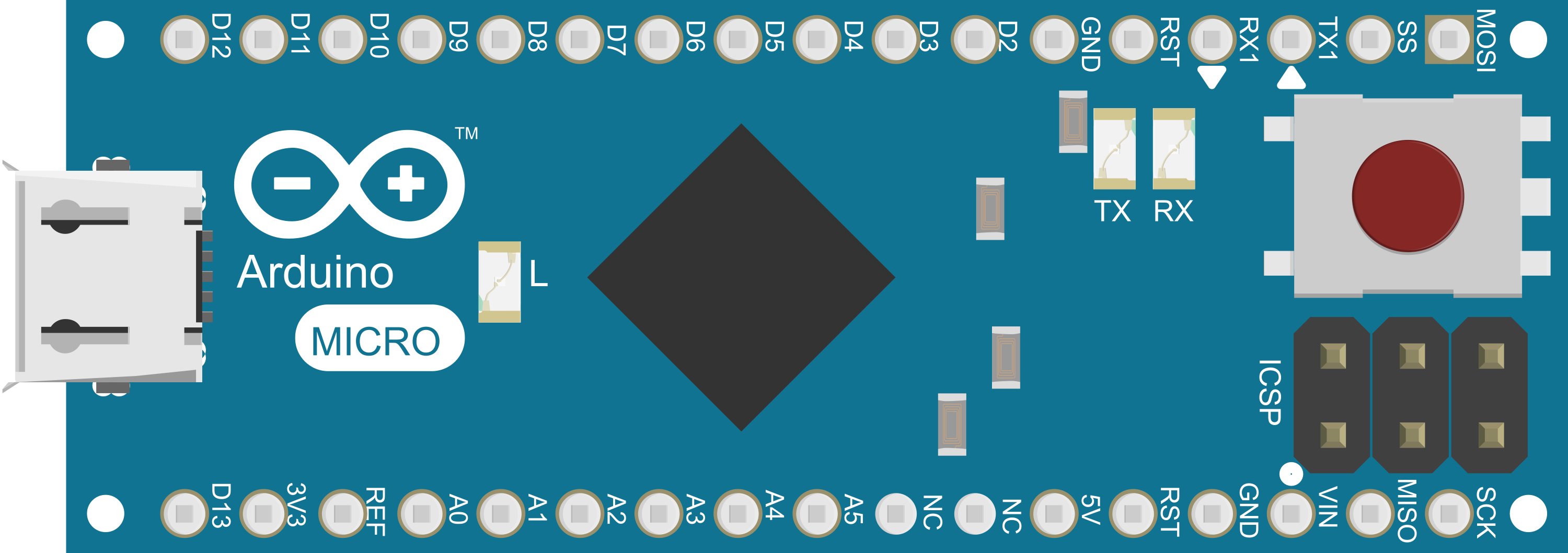
Pin Configuration and Descriptions

Pin Number Function Description
1-7 Digital I/O Digital pins capable of input/output functions.
8-10 PWM Support for Pulse Width Modulation.
14-20 Analog Input Analog pins which can read varying voltages.
21 RESET Used to reset the microcontroller.
22-23 I2C SDA and SCL pins for I2C communication.
24 RX/TX LEDs Indicators for serial communication.
25 USB Connection Micro USB port for power and data.
26 ICSP Header In-Circuit Serial Programming header.
27 3.3V 3.3V power output (limited current).
28 5V Regulated 5V power supply pin.
29 GND Ground pins.
30 Vin Input voltage to the Arduino board.

Usage Instructions

How to Use the Component in a Circuit

  1. Powering the Board:

    • Connect the board to a computer via a Micro USB cable to power it directly.
    • Alternatively, supply power through the Vin pin with an external power source between 7-12V.
  2. Programming the Board:

    • Install the Arduino IDE from the official Arduino website.
    • Connect the Arduino Micro to your computer using a Micro USB cable.
    • Select 'Arduino Micro' from the Tools > Board menu in the Arduino IDE.
    • Write your sketch (program) and upload it to the board using the IDE.
  3. Connecting I/O Devices:

    • Use the digital and analog pins to connect sensors, actuators, and other components.
    • Ensure that the components you connect are rated for the operating voltage and current of the pins.

Important Considerations and Best Practices

  • Always disconnect the board from power sources before making or altering connections.
  • Do not exceed the recommended voltage and current ratings to avoid damaging the board.
  • Use a current limiting resistor when connecting LEDs to the output pins.
  • Utilize the onboard LED connected to pin 13 for testing and debugging purposes.
  • When using PWM pins, ensure that the connected devices are compatible with PWM signals.

Troubleshooting and FAQs

Common Issues Users Might Face

  • Board not recognized by the computer:

    • Check the USB cable and port.
    • Ensure the correct drivers are installed.
    • Try resetting the board by briefly pressing the reset button.
  • Sketch not uploading:

    • Verify that the correct board and port are selected in the Arduino IDE.
    • Check for errors in the code that may prevent compilation.
    • Ensure the bootloader is functioning correctly.
  • Unexpected behavior in circuits:

    • Double-check wiring and connections.
    • Ensure power supply stability and adequacy.
    • Review the code for logical errors or incorrect pin assignments.

Solutions and Tips for Troubleshooting

  • Use the Arduino IDE's Serial Monitor to debug and print out messages from the board.
  • Isolate the problem by reducing the circuit to its simplest form and gradually adding components.
  • Consult the Arduino forums and community for support and advice.

Relevant Code Example for Arduino UNO

Here's a simple example of blinking the onboard LED:

// Pin 13 has an LED connected on most Arduino boards.
int led = 13;

// The setup routine runs once when you press reset:
void setup() {                
  // Initialize the digital pin as an output.
  pinMode(led, OUTPUT);     
}

// The loop routine runs over and over again forever:
void loop() {
  digitalWrite(led, HIGH);   // Turn the LED on (HIGH is the voltage level)
  delay(1000);               // Wait for a second
  digitalWrite(led, LOW);    // Turn the LED off by making the voltage LOW
  delay(1000);               // Wait for a second
}

Remember to wrap code comments as needed to limit line length to 80 characters. This helps maintain readability in various editors and documentation formats.