The SW-420 Vibration Sensor is a simple and cost-effective module designed to detect vibrations and shocks. It is based on the principle of a conductive ball inside a tube that makes contact with pins when the sensor is moved, thus closing the circuit. This sensor is widely used in applications such as burglar alarms, car alarms, smart vehicles, earthquake detection systems, and other systems where vibration or impact detection is required.
Explore Projects Built with SW-420 Vibration Sensor
Use Cirkit Designer to design, explore, and prototype these projects online. Some projects support real-time simulation. Click "Open Project" to start designing instantly!
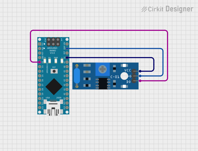
This circuit connects an SW-420 Vibration Sensor to an Arduino Nano. The vibration sensor's digital output is linked to the Arduino's D2 pin, allowing the microcontroller to detect vibrations. The sensor is powered by the Arduino's 5V output, and both devices share a common ground.
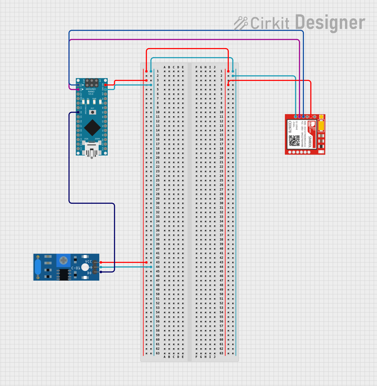
This circuit is designed to detect vibrations using the SW-420 Vibration Sensor and communicate the detection events via the Sim800l GSM module. The Arduino Nano serves as the central controller, interfacing with the vibration sensor on its digital pin D4 and with the Sim800l module through serial communication using pins D0/RX and D1/TX. The circuit is likely intended for remote monitoring of vibrations, potentially for security or machinery fault detection applications.
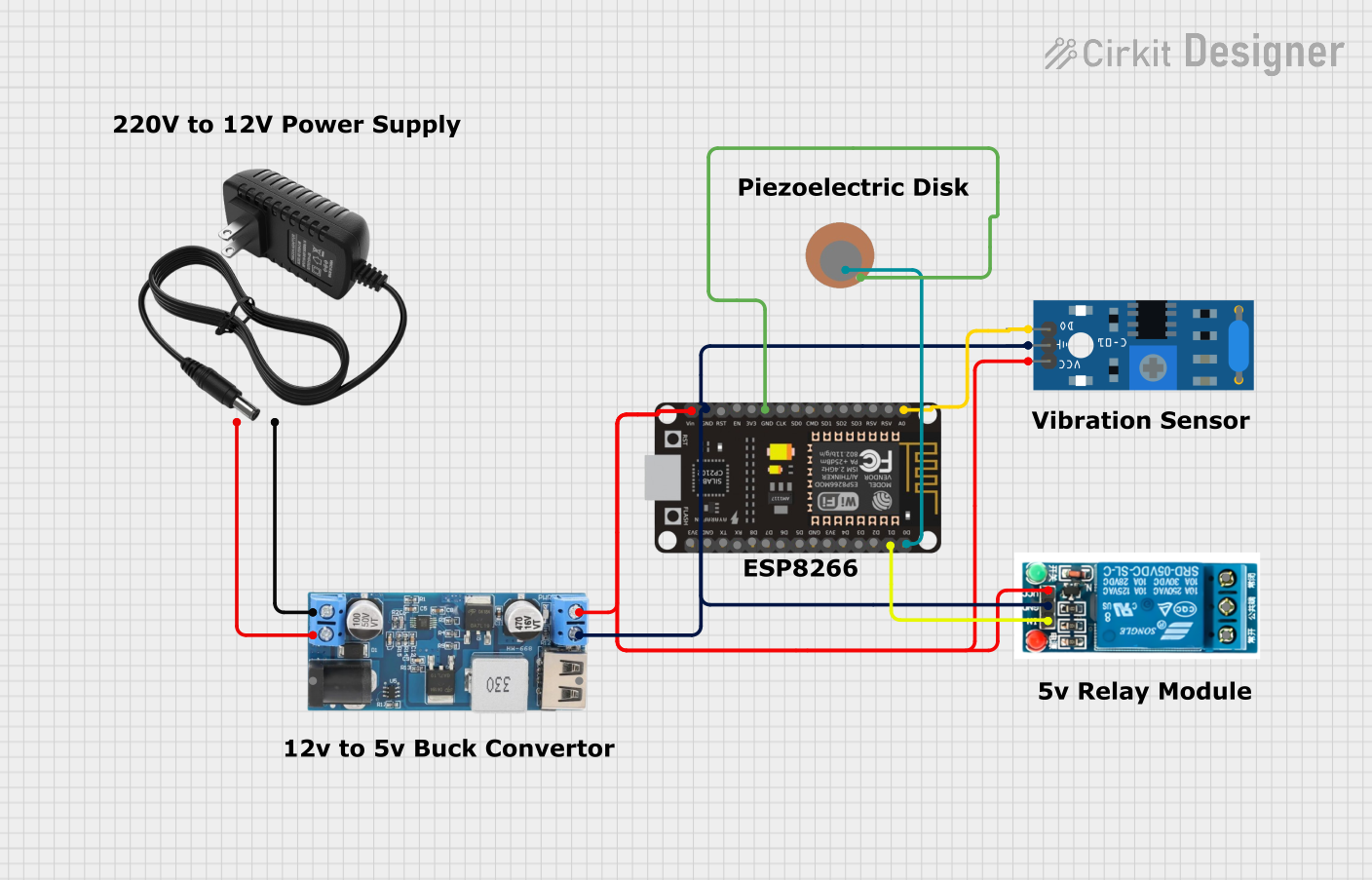
This circuit is a vibration detection system that uses an SW-420 vibration sensor and a piezo sensor to detect vibrations and trigger a 5V relay. The system is controlled by an ESP8266 NodeMCU, which processes the sensor inputs and controls the relay. A 12V power supply is stepped down to 5V to power the components.
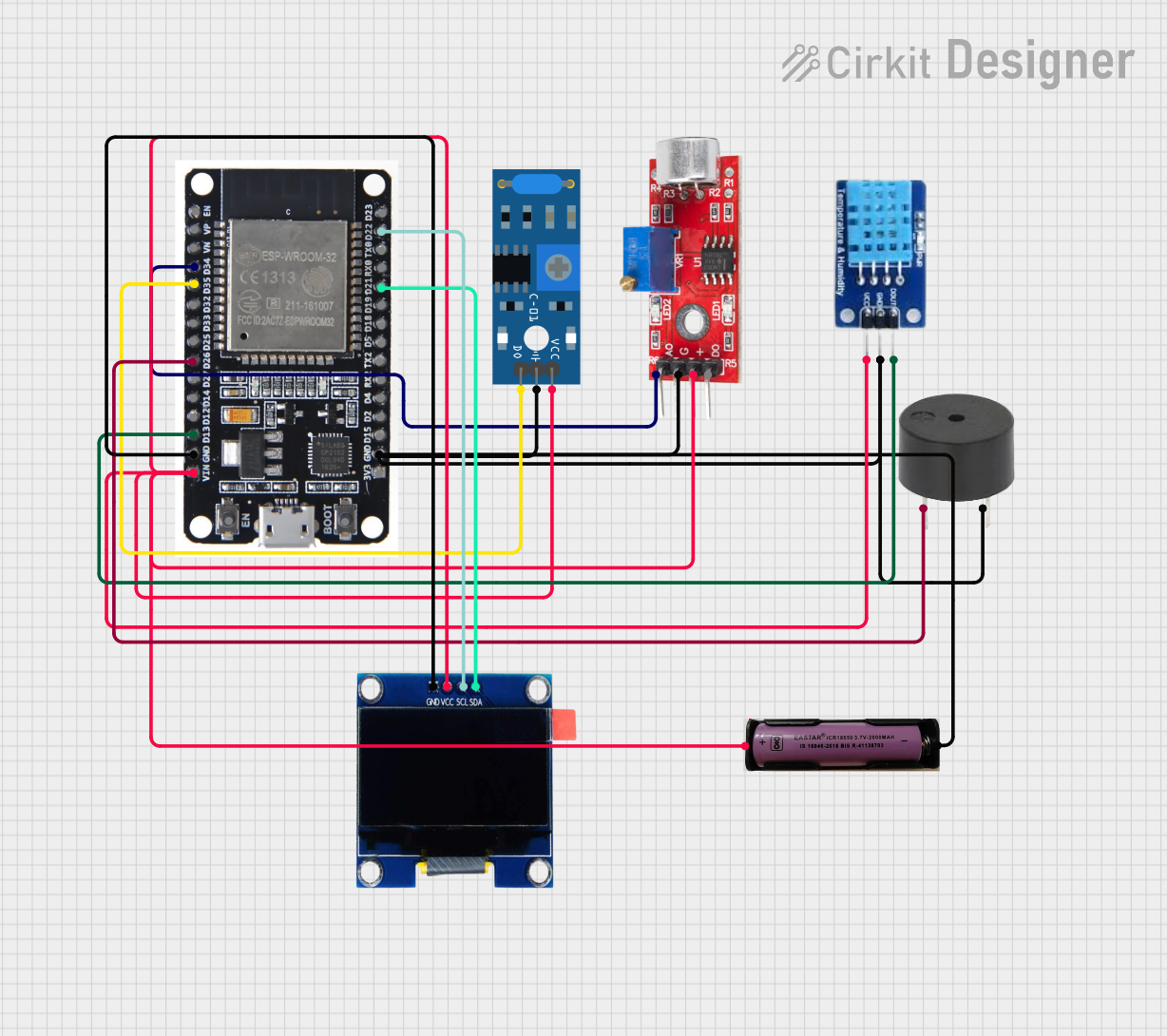
This circuit features an ESP32 microcontroller connected to various sensors and output devices. A sound sensor and a SW-420 vibration sensor provide analog and digital inputs, respectively, to the ESP32 for environmental monitoring. The circuit also includes a DHT11 sensor for temperature and humidity readings, a buzzer for audible alerts, and an OLED display for visual feedback, all interfaced with the ESP32. Power is supplied by a 3.7V source connected to all components requiring VCC.
Connect the VCC pin to the positive supply voltage (3.3V to 5V).
Connect the GND pin to the ground of the power supply.
The DO pin outputs a digital signal and should be connected to a digital input pin on a microcontroller like an Arduino UNO.
Important Considerations and Best Practices
Ensure that the power supply voltage does not exceed the recommended operating voltage to prevent damage to the sensor.
The sensor's sensitivity can be adjusted using the onboard potentiometer. Turn clockwise to increase sensitivity and counterclockwise to decrease it.
Avoid placing the sensor in an environment with constant vibration as it may lead to false triggers.
Use a pull-up resistor if the microcontroller input pin does not have an internal pull-up feature.
Example Code for Arduino UNO
// Define the pin where the sensor is connected
const int vibrationSensorPin = 2;

void setup() {
  // Initialize the sensor pin as an input
  pinMode(vibrationSensorPin, INPUT);
  // Begin serial communication at a baud rate of 9600
  Serial.begin(9600);
}

void loop() {
  // Read the state of the vibration sensor
  int sensorState = digitalRead(vibrationSensorPin);

  // Check if the sensor is triggered
  if (sensorState == HIGH) {
    // If the sensor is triggered, print a message to the serial monitor
    Serial.println("Vibration detected!");
  } else {
    // If the sensor is not triggered, print a different message
    Serial.println("No vibration detected.");
  }

  // Wait for a short period before reading again
  delay(100);
}
Troubleshooting and FAQs
Common Issues
Sensor not responding: Ensure that all connections are secure and the power supply is within the specified range.
False triggers or no detection: Adjust the sensitivity using the onboard potentiometer. Environmental factors such as wind or machinery can cause false triggers.
Inconsistent readings: Check for loose connections and ensure the sensor is mounted securely to prevent random vibrations.
Solutions and Tips
If the sensor is too sensitive, try placing it on a more stable surface or decrease the sensitivity using the potentiometer.
For a more robust application, consider implementing a software debounce to filter out spurious signals.
When integrating with a microcontroller, ensure that the input pin is configured correctly and that the sensor's digital output is compatible with the logic level of the microcontroller.
FAQs
Q: Can the SW-420 Vibration Sensor detect the direction of vibration?
A: No, the SW-420 can only detect the presence of vibration, not its direction.
Q: Is it possible to use the SW-420 sensor with a battery?
A: Yes, as long as the battery voltage is within the operating range of 3.3V to 5V.
Q: How can I extend the life of the sensor?
A: Avoid exposing the sensor to continuous vibrations and extreme temperatures to prolong its lifespan.
Q: Can I use the SW-420 sensor with an analog input?
A: The SW-420 provides a digital output and is not designed for analog input. However, some modules may come with an analog output; refer to the specific module datasheet for details.


 Open Project in Cirkit Designer