How to Use USB-CAN-A: Examples, Pinouts, and Specs
Introduction
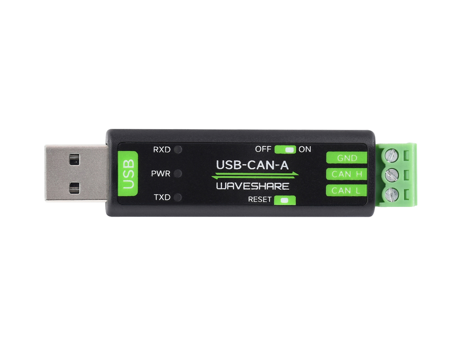
The USB-CAN-A is a versatile USB to CAN (Controller Area Network) adapter manufactured by Waveshare. This component enables a computer to communicate with CAN bus systems, which are widely used in automotive and industrial applications. The USB-CAN-A adapter is essential for tasks such as vehicle diagnostics, industrial automation, and embedded system development.
Explore Projects Built with USB-CAN-A

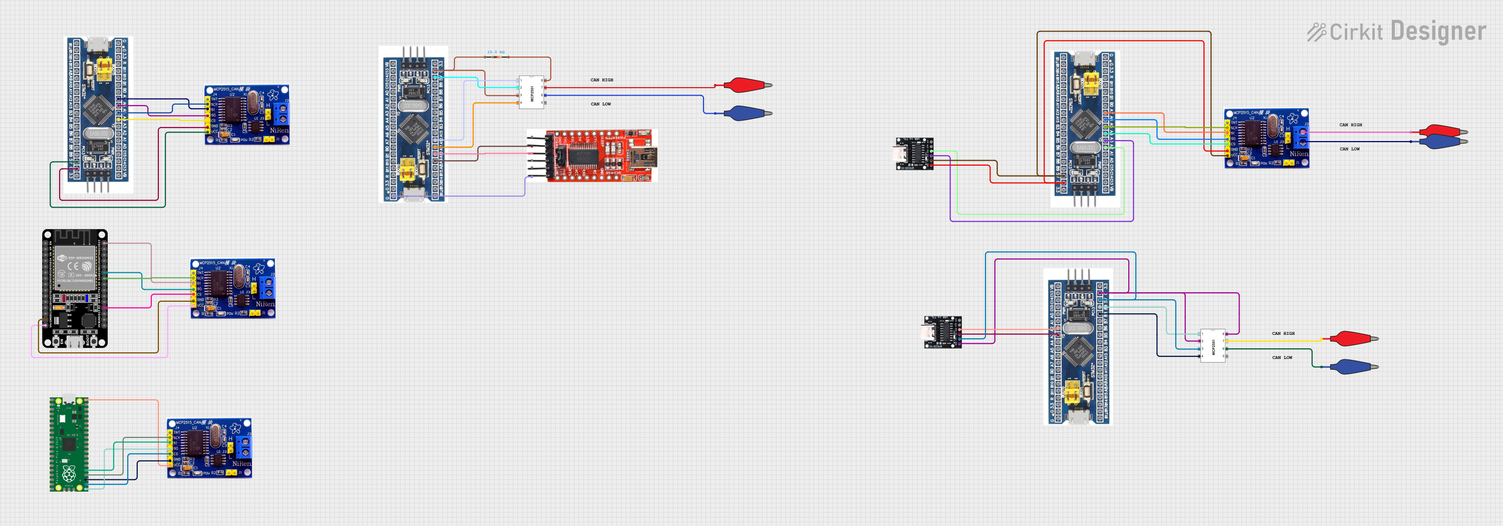

Explore Projects Built with USB-CAN-A
Technical Specifications
Key Technical Details
| Parameter | Value |
|---|---|
| Manufacturer | Waveshare |
| Model | USB-CAN-A |
| Interface | USB 2.0 |
| CAN Interface | CAN 2.0A/B |
| Baud Rate | 5 kbps to 1 Mbps |
| Power Supply | 5V (via USB) |
| Operating Current | < 100 mA |
| Operating Temperature | -40°C to 85°C |
| Dimensions | 60mm x 30mm x 12mm |
Pin Configuration and Descriptions
| Pin Number | Pin Name | Description |
|---|---|---|
| 1 | CAN_H | CAN High Signal |
| 2 | CAN_L | CAN Low Signal |
| 3 | GND | Ground |
| 4 | VCC | Power Supply (5V via USB) |
| 5 | USB | USB Interface for PC Connection |
Usage Instructions
How to Use the Component in a Circuit
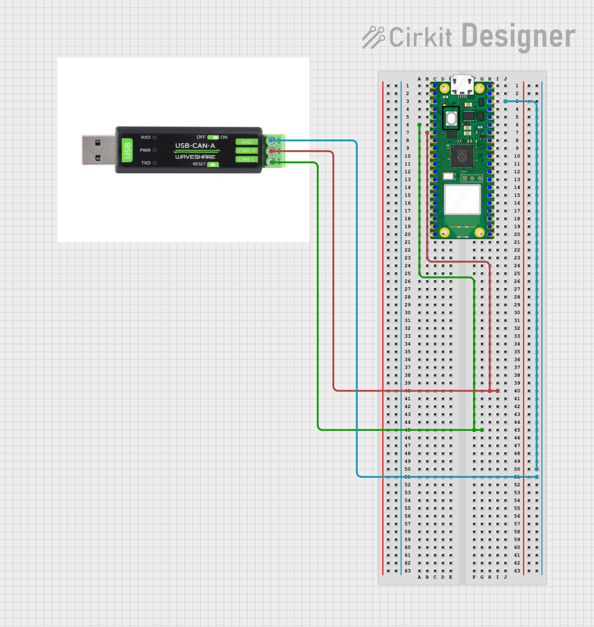
Connect the USB-CAN-A to the Computer:
- Plug the USB-CAN-A adapter into an available USB port on your computer.
- Install the necessary drivers provided by Waveshare.
Connect to the CAN Bus:
- Connect the CAN_H pin to the CAN high line of your CAN bus.
- Connect the CAN_L pin to the CAN low line of your CAN bus.
- Ensure the GND pin is connected to the ground of your CAN bus system.
Software Setup:
- Use compatible software (e.g., PCAN-View, CANalyzer) to configure and monitor the CAN bus communication.
- Set the appropriate baud rate and other parameters as required by your CAN network.
Important Considerations and Best Practices
- Termination Resistor: Ensure that the CAN bus is properly terminated with a 120-ohm resistor at each end of the bus to prevent signal reflections.
- Power Supply: The USB-CAN-A is powered via the USB port, so no external power supply is needed.
- Driver Installation: Always use the latest drivers provided by Waveshare to ensure compatibility and performance.
- Baud Rate Configuration: Match the baud rate of the USB-CAN-A with the baud rate of the CAN bus to ensure proper communication.
Troubleshooting and FAQs
Common Issues Users Might Face
No Communication with CAN Bus:
- Solution: Check the connections of CAN_H and CAN_L. Ensure the CAN bus is properly terminated with 120-ohm resistors at both ends.
Driver Installation Problems:
- Solution: Ensure you have downloaded the correct drivers from the Waveshare website. Try reinstalling the drivers and restarting your computer.
Incorrect Baud Rate:
- Solution: Verify that the baud rate set in the software matches the baud rate of the CAN bus. Mismatched baud rates can prevent communication.
Power Issues:
- Solution: Ensure the USB port is providing sufficient power. Try using a different USB port or a powered USB hub.
Solutions and Tips for Troubleshooting
- Check Connections: Always double-check the physical connections of the CAN_H, CAN_L, and GND pins.
- Update Software: Ensure that both the driver and the CAN monitoring software are up to date.
- Consult Documentation: Refer to the Waveshare documentation and user manual for detailed instructions and troubleshooting tips.
Example Code for Arduino UNO
If you are using the USB-CAN-A with an Arduino UNO, you can use the following example code to send and receive CAN messages. Note that you will need an additional CAN shield for the Arduino to interface with the CAN bus.
#include <SPI.h>
#include <mcp2515.h>

struct can_frame canMsg;
MCP2515 mcp2515(10); // Set CS pin to 10

void setup() {
  Serial.begin(115200);
  mcp2515.reset();
  mcp2515.setBitrate(CAN_500KBPS, MCP_8MHZ); // Set CAN bitrate
  mcp2515.setNormalMode();
}

void loop() {
  // Send CAN message
  canMsg.can_id  = 0x036; // CAN ID
  canMsg.can_dlc = 2;     // Data length
  canMsg.data[0] = 0x01;  // Data byte 1
  canMsg.data[1] = 0x02;  // Data byte 2
  mcp2515.sendMessage(&canMsg);

  // Receive CAN message
  if (mcp2515.readMessage(&canMsg) == MCP2515::ERROR_OK) {
    Serial.print("CAN ID: ");
    Serial.println(canMsg.can_id, HEX);
    Serial.print("Data: ");
    for (int i = 0; i < canMsg.can_dlc; i++) {
      Serial.print(canMsg.data[i], HEX);
      Serial.print(" ");
    }
    Serial.println();
  }

  delay(1000); // Delay for 1 second
}
This code initializes the CAN bus at a 500 kbps baud rate, sends a CAN message with ID 0x036, and listens for incoming CAN messages. Make sure to adjust the CAN ID and data bytes as needed for your application.
By following this documentation, you should be able to effectively use the USB-CAN-A adapter in your CAN bus projects. For further assistance, refer to the Waveshare user manual and support resources.