How to Use Altera DE-10 lite: Examples, Pinouts, and Specs
Introduction
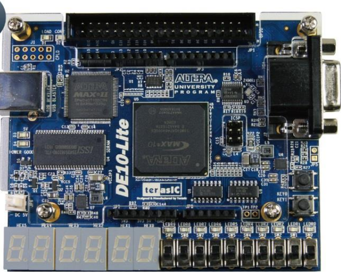
The Altera DE-10 Lite is a feature-rich FPGA development board designed for users who require a platform for digital design and prototyping. Equipped with an Intel Cyclone V FPGA, the DE-10 Lite provides a robust hardware environment for designers to accelerate the development process and test their FPGA designs. Common applications include digital signal processing, image processing, embedded systems, and educational purposes for learning digital logic and computer architecture.
Explore Projects Built with Altera DE-10 lite
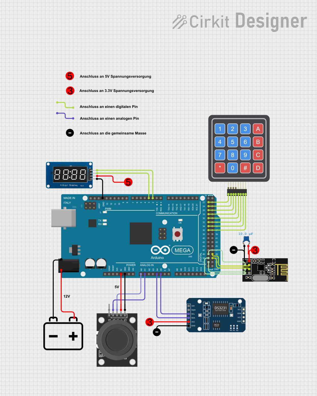
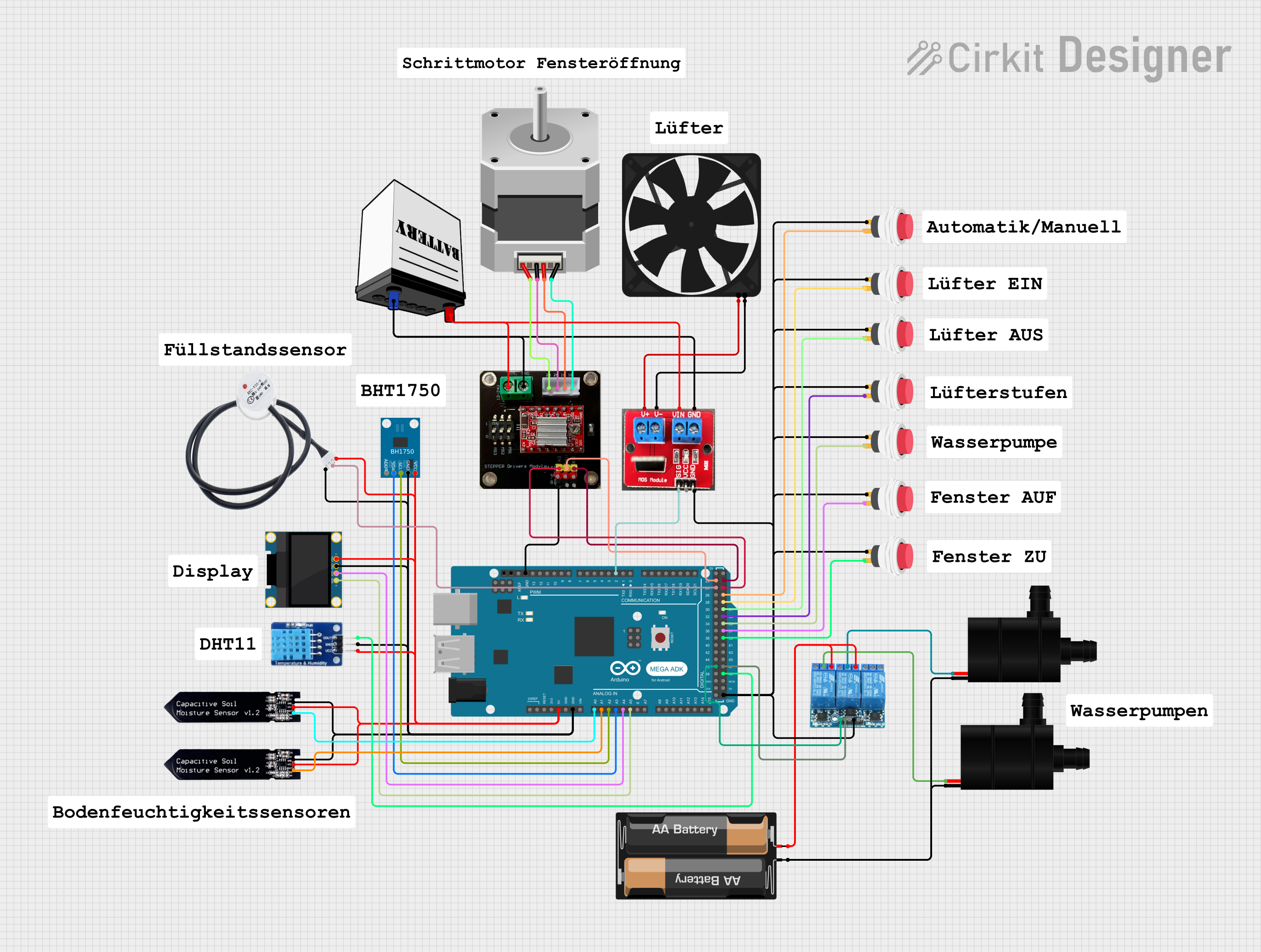
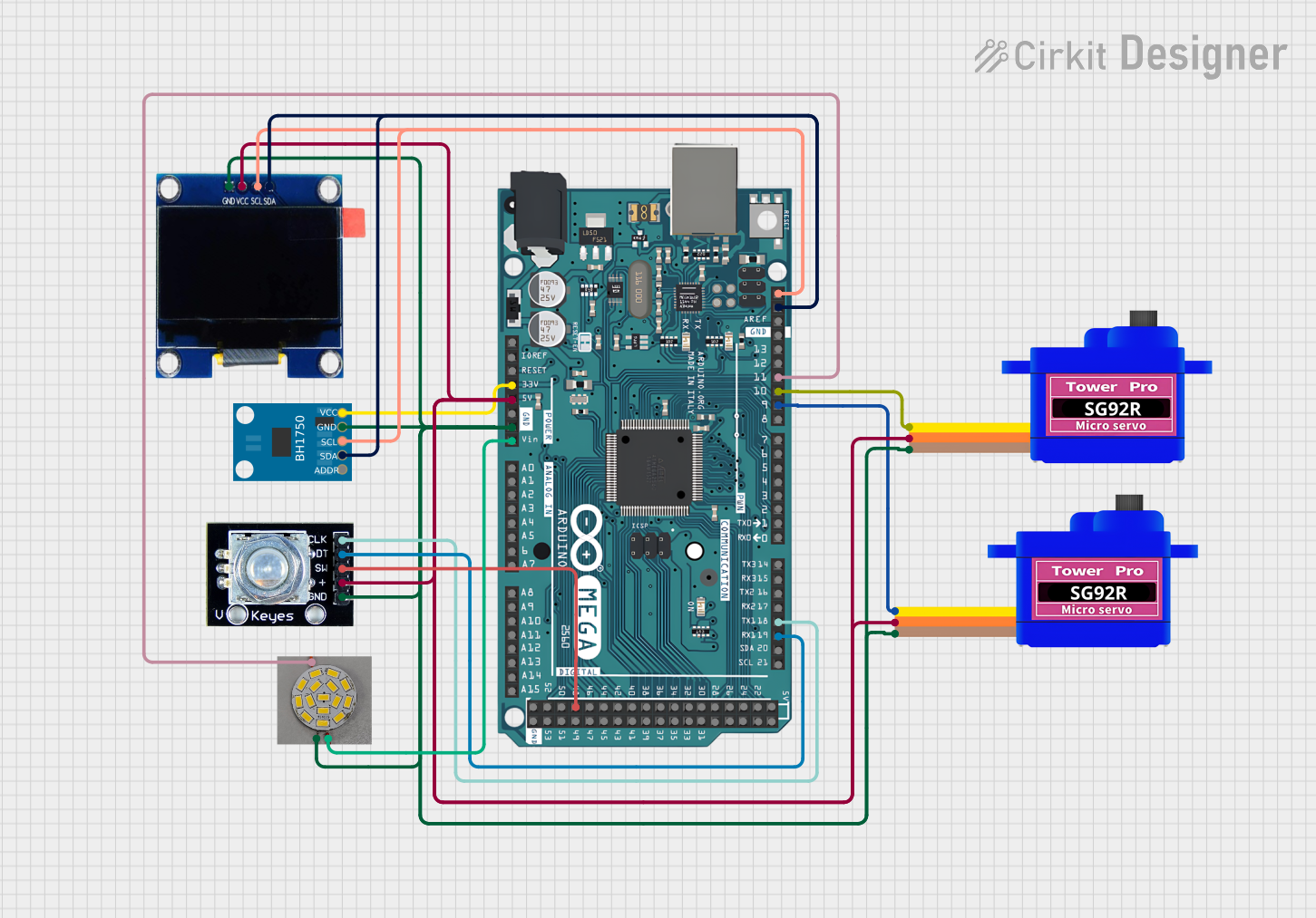

Explore Projects Built with Altera DE-10 lite
Technical Specifications
Key Features
- FPGA: Intel Cyclone V 5CSELT6 FPGA
- Logic Elements: 30,000
- Memory: 32 MB SDRAM, 2 KB EEPROM
- Clock Speed: 50 MHz onboard oscillator
- Connectors: Two 40-pin General Purpose I/O (GPIO) headers
- Display Interface: VGA connector
- Audio: 24-bit CODEC, line-in, line-out, and microphone-in jacks
- User Interface: 10 switches, 10 LEDs, 2 seven-segment displays
- Programming: USB-Blaster (onboard) for FPGA programming
Pin Configuration and Descriptions
| Pin Number | Description | Notes |
|---|---|---|
| 1 | 3.3V Power Supply | |
| 2-41 | GPIO Header 1 | 40-pin header for GPIO signals |
| 42-81 | GPIO Header 2 | 40-pin header for GPIO signals |
| 82 | Ground (GND) | |
| 83 | VGA Red | VGA output |
| 84 | VGA Green | VGA output |
| 85 | VGA Blue | VGA output |
| 86 | VGA Horizontal Sync | VGA output |
| 87 | VGA Vertical Sync | VGA output |
| 88 | Audio Line-In | 24-bit CODEC |
| 89 | Audio Line-Out | 24-bit CODEC |
| 90 | Audio Mic-In | 24-bit CODEC |
| 91-100 | User Switches (SW0-SW9) | Input switches |
| 101-110 | User LEDs (LED0-LED9) | Output LEDs |
| 111-118 | Seven-Segment Display (HEX0) | Output seven-segment display |
| 119-126 | Seven-Segment Display (HEX1) | Output seven-segment display |
Note: This is a simplified pin configuration. Refer to the DE-10 Lite User Manual for a complete pinout and detailed descriptions.
Usage Instructions
Setting Up the DE-10 Lite
- Connect the DE-10 Lite to a power source using the provided power adapter.
- Connect the USB-Blaster port to your computer for FPGA programming.
- Install the required software (Quartus Prime) and drivers for the DE-10 Lite.
Programming the FPGA
- Create a new project in Quartus Prime for the DE-10 Lite board.
- Design your logic circuit using VHDL or Verilog, or use provided sample projects.
- Compile the design and ensure there are no errors.
- Program the FPGA using the onboard USB-Blaster.
Best Practices
- Always ensure the board is powered off before connecting or disconnecting any peripherals.
- Double-check pin assignments and configurations before programming the FPGA to prevent damage.
- Use proper ESD precautions when handling the board to avoid static damage to the FPGA and other components.
Troubleshooting and FAQs
Common Issues
- FPGA not recognized by the computer: Ensure that the USB-Blaster drivers are correctly installed and that the USB cable is properly connected.
- Design does not behave as expected: Verify the logic design, simulation results, and pin assignments. Ensure that the FPGA was successfully programmed without errors.
FAQs
Q: Can I use the DE-10 Lite with an Arduino UNO?
- A: The DE-10 Lite is not directly compatible with Arduino UNO boards, but you can interface them using the GPIO headers and appropriate level shifting.
Q: What software is needed to program the DE-10 Lite?
- A: Intel's Quartus Prime software is used for FPGA development and programming.
Q: How do I reset the FPGA to its default state?
- A: You can reset the FPGA by pressing the onboard reset button or by reprogramming it with a blank project.
For more detailed troubleshooting, refer to the DE-10 Lite User Manual and support forums.
Note: This documentation is a simplified guide to the Altera DE-10 Lite development board. For comprehensive information, always refer to the official documentation provided by Intel.